What time and date is it?

After my vacation I finally found the time to extend my DCF77 project to the next stage. The previous version was only able to decode the time and did not properly deal with leap seconds. The new version fixes all these issues. It will decode “everything” and take care of “everything”. That is it properly handles daylight saving and leap seconds. It also determines the date and the weekday.

C08_Clock_Architecture_with_flags_and_encoder

At first glance it seems that I just added more “decoder boxes” but have a look at the top of the architecture diagram. Now I also require an encoder box. That is my clock can locally synthesize a valid DCF77 code. This was necessary to deal with the messy details of leap seconds. So have a look at my newest version and find out how to do this.

By the way: as far as I know this is the only open DCF77 clock with this level of error correction. If anyone knows another project that goes so far (or further) I would be pleased to learn about it. Please drop me an email or leave a comment on this page.

Posted in Uncategorized | Leave a comment

A Travel Hack

This month I was on vacation. Therefore the post to this month’s hack is slightly delayed. Nevertheless the people who follow my blog where able to see the content page at the first of the month. So in case you never want to miss my new pages you might want to follow my blog. Just use the “sign me up” button in the sidebar to the right.

As I said I was on vacation. I was travelling to the US and this brought up again the never ending travel adapter issue. My final fix is somewhat unusal. It is hackish in nature but trivial to execute. My first solution was already very satisfactory:

DIY Travel Adapter

DIY Travel Adapter

But it pales to the final IEC compliant solution. You might find it trivial but I am very proud of it for exactly that reason. Once you know this solution it is as obvious as can be. But if you do not know it you might not even suspect that it exist

Posted in Uncategorized | Leave a comment

What time is it?

After last month’s Lighthouses experiment I am back on track with my DCF77 clock. The Second Decoder is now extended with additinal decoders for decoding time data.

From the architecture point of view this adds just two more boxes.

Decoding Hours and Minutes

But don’t be fooled. These two boxes have a quite different construction from the second decoder. The other decoder boxes that are still missing will rely on the same inner workings. All of them will utilize a hamming metric based approach.

The software part of the project is getting closer to its final stage:

  1. Exponential filtering of the signal
  2. Phase locked loop / optimal filter for 1Hz phase reconstruction
  3. Reconstruction of the seconds
  4. Hamming metric based reconstruction of the data
  5. Dealing with signal loss

Finally my clock can decode the current time . So next month I can take care of the date 😉

With regard to the antenna hardware I finished reading the books:

Das neue Magnetantennenbuch: Selbstbau-Loops für Sende- und Empfangsbetrieb

Außergewöhnliche Empfangsantennen und ihre Anpassung für den Längst- und Kurzwellenbereich

Since this created a desire for more I started to read this one as well:

Rothammels Antennenbuch

My summary so far:

  1. The best amplifier is a better antenna.
  2. Bigger is better.
  3. There is more to learn about antennas than you might expect.
Posted in Uncategorized | Leave a comment

Light my Fires

My DCF77 project is making good progress. However it will require at least 3 more articles. So I thought I should give it a short break. After all this project drifts a little bit to the signal processing side.

So this month I will focus a little bit more on the Blinkenlight aspects again. The motivation is taken from a question in the German Arduino forum. The question was how to simulate a bunch of light houses / light fires for a nautic map.

One approach would be to encode this in the style of my persistence of vision experiments and reduce the sample rate. However this confuses the actual blink rates and makes the code somewhat hard to adapt to new blink rates.

Thus I implemented a short light houses sketch.

Lighthouses

In my opinion the resulting code is pretty nifty. I especially like the fact there there are no explicit loop constructs for the blinking.

Posted in Uncategorized | Leave a comment

The Second Decoder

This is the second post for this year. And it is the second part of the improved DCF77 decoder. And it decodes seconds. So I think it is most appropriate to call this the Second Decoder.

I even renumbered my project plan to make the second decoder #2 on the list.

  1. Exponential filtering of the signal
  2. Phase locked loop / optimal filter for 1Hz phase reconstruction
  3. Reconstruction of the seconds
  4. Hamming metric based reconstruction of the data
  5. Dealing with signal loss

This decoder is crucial as knowing the correct second is key to decoding the actual time data. See the picture below for an overview or read my DCF77 introduction.

DCF77 Code

DCF77 Code

While I am pushing forward with the software I am now also considering improvements to the hardware. There are two directions I am following. I am evaluating different DCF77 decoder modules and I am looking into improved antenna design. Right now I am reading the following two books:

Das neue Magnetantennenbuch: Selbstbau-Loops für Sende- und Empfangsbetrieb

Außergewöhnliche Empfangsantennen und ihre Anpassung für den Längst- und Kurzwellenbereich

The point here is that the antenna can make a big difference. Once I am through this stuff I will cover it on my blog as well.

For now click here for the Second Decoder.

Posted in Uncategorized | Leave a comment

Happy New Year DCF77 Project – Get ready for the real thing!

Last year I started my binary clock project for the Blinkenlighty.

This project gathered significant attention. Of course a lot is to be attributed to the project being mentioned by Hackaday. However this attention usually settles quickly. The DCF77 project though gets lots of revisits. Decembber 2012 was the first month ever with >20 000 page hits on my blog 🙂

The article also caused lively discussions in the Germany Arduino Forum. I am especially grateful for the experiments by Jurs. He benchmarked my first implementation with some DCF77 clock modules. As it turns out the different modules are not so similar as one might expect. His main point though was that my first implementation might only be marginally better than the better commercial modules. This is excellent news because now I can use the first implementation as a benchmark.

2013 I am really going to push the limits for DCF77 clock decoding on an Arduino. This will be quite hard for me as my DCF77 investigations are somewhat sabotaged by a Robbe Blue Arrow. I got this quadcopter for Christmas and is definitely a lot of fun. So I spent a lot of time practising.

But back to my project. In case you want to understand the theory behind my approach you might want to have a look into Digital Signal Processing. A Practical Guide for Engineers and Scientists by Steven Smith as well as Information Theory, Inference, and Learning Algorithms by David MacKay.

Alternatively you might want to read the original work of the Claude Elwood Shannon himself: A Mathematical Theory of Communication and Communication in the Presence of Noise. These papers are really striking. You have to look at the date when they were published to fully appreciate this scientific master piece. In addition these papers are very unusual as they are comparatively easy to follow.

In case you do not read (or do not understand) this stuff. Do not worry. The code will work anyway 😉

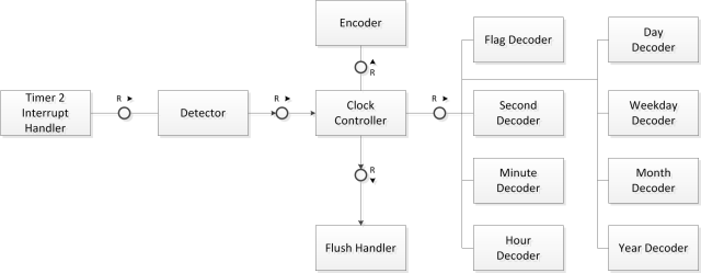
So let’s continue with step 2 of the project plan.

  1. Exponential filtering of the signal
  2. Phase locked loop / optimal filter for 1Hz phase reconstruction
  3. Reconstruction of the seconds
  4. Hamming metric based reconstruction of the data
  5. Dealing with signal loss

The result will be a phase locked 1 Hz pulse. Not excited? You could do this with less than half a page of code? Think about it again. I did not say approximately 1 Hz. As long as the code has a DCF77 phase lock it will be exactly 1 Hz (with at most 10 ms jitter). And this will work even in the presence of significant noise. Not yet impressed? Then have a look how the exponential filter performs are 80% noise vs. the new approach at more 95% noise and even more.

C05_bins_noise_95_1000

One final word before you go to the article and play around with my code. As it turns out a good local clock is absolutely mandatory. It follows that your Arduino must have a crystal. resonator based clocks are to inaccurate for our purposes. Especially the modern Arduino Uno has a clock that is to crappy for our purposes. So ensure that your Arduino is build on the “outdated” Duemilanove (or older) design. To make this absolutely clear: “outdated” means more expensive to manufacture. Just like the Blinkenlighty 😉

Posted in Uncategorized | Leave a comment

2012 in review

The WordPress.com stats helper monkeys prepared a 2012 annual report for this blog.

Here’s an excerpt:

19,000 people fit into the new Barclays Center to see Jay-Z perform. This blog was viewed about 140,000 times in 2012. If it were a concert at the Barclays Center, it would take about 7 sold-out performances for that many people to see it.

Click here to see the complete report.

Or with other words: WordPress knows how to lie with statistics. After all some people view more than one page ;). Follow the link or click on the picture if you want to see the numbers anyway 🙂

Happy New Year 2013!

Posted in Uncategorized | Leave a comment

DCF77 Project

This month I will start a series of experiments geared to develop a DCF77 clock decoder. The idea is of course to establish a binary clock for the Blinkenlighty.

You might wonder why I need a series of experiments for this. After all there are quite some DCF77 libraries readily available for download. Some are even featured in the Arduino playground.

The point is that they all perform very poor in the presence of noise. Unfortunately the DCF77 signal is almost always noisy. So my goal is to develop the most noise tolerant DCF77 clock decoder software ever.

As it turns out this is significantly harder as it appears at the first glance. Hence I will progress in steps that are hopefully not to hard to swallow.

My plan is to start with a standard library and then to refine it gradually:

  1. Exponential filtering of the signal
  2. Phase locked loop / optimal filter for 1Hz phase reconstruction
  3. Reconstruction of the seconds
  4. Hamming metric based reconstruction of the data
  5. Dealing with signal loss
  6. Tuning the crystal

Step (0) will already produce clocks that has superior filtering compared to most. After step (3) however we will have unprecedented noise resilence. An early prototype already locked to a signal with >80% noise – Something that is completely out of reach for any simple decoder.

Ironically there will be no video for the first stages of these experiments because my photo lights creates to much noise for the DCF77 receiver to demodulate any signal at all. No matter how much denoising is present, if there is no demodulated signal the clock has absolutely no chance.

Click on the diagrams to learn how I apply exponential filtering to improve an existing library.

Noise vs. Filters

In case you want to dig deeper into what I am going to do I strongly recommend the book Digital Signal Processing. A Practical Guide for Engineers and Scientists by Steven Smith. I also find Information Theory, Inference, and Learning Algorithms by David MacKay very inspiring. Basically I follow the ideas that you can find in these two books. A word of warning though: if you have no knowledge of mathematics they are not exactly an easy read 😉

Posted in Uncategorized | 6 Comments

The Blinkenlighty

As I already anounced last month there is now an Arduino clone designed by me. This month it finally got available in numbers. Since the board was released in Germany I have run a small naming contest in the German Arduino Forum. The contest was won by Forum Member “Addi”. The “official” name for my clone is now “Blinkenlighty”. Click on the picture to find out more details on the schematic and the layout.

If you want to buy it, it is available as part of the Franzis Lernpaket “Lichteffekte mit Arduino”.

The “Lernpaket” does not only contain a Blinkenlighty but also a book by me. The book contains some experiments I did not publish on my webpage. It also contains some details about the inner workings of the Arduino that seem not be generally known. In addition I cover some very cool Blinkinglight effects. Have a look at the videos. The effects are ***very*** smooth because it is PWM with 8 bit resolution at more than 20 kHz.

Of course this month’s experiment will utilize the Blinkenlighty. In the Arduino forum every once in a while there is the question how to measure the supply voltage. As it turns out this is pretty simple. The controller has a built in voltage reference which can be measured relative to the supply voltage. Since the voltage of the reference is known this can then be used to compute the supply voltage. Read my supply voltage measurement experiment on how to implement this.

Posted in Uncategorized | Leave a comment

Power Grid Monitoring Revisited

My first take on monitoring the power grid was basically focused on clever exploitation of the capabilities the Blinkenlight Shield. As it turned out this gives a really nice experiment.

However some of my readers commented that they would have expected a means for frequency measurement. Mostly because this would allow them to modify the code for their own purposes. So here it is. The new Power Grid Monitor 2 Experiment.

Power Grid Monitoring

This new experiment really samples the grid frequency and uses the Blinkenlight Shield as some rudimentary display. Although this is much more of a real measurement I still like the old display much better 😉

One final word for this month. Some of you may already have noticed that you can not buy the shield from Rugged Circuits anymore. This is because I signed a contract with “Franzis” Germany. This basically gives them the exclusive right to manufacture and sell my shields. They also sell a special Arduino clone (designed by me) that has an integrated Blinkenlights. It also comes with a book written by me and a CD with lots of additional background material. The book contains some details and experiments that you can not find on my website. I hope this eventually makes my designs available to more people. The revenue also helps to fund my website. Still I stick to the open source idea. That is although they have exclusive commercial rights we negotiated that everything on my website will be available under the smae license terms as before.

Posted in Uncategorized | Leave a comment