
This is the second part of my DCF77 experiments. It is also the first step in the direction of a significantly better DCF77 decoder. Because the improved decoder is signifcantly more complex I will proceed in smaller steps. The first step introduces a so called phase lock. Before I go into the details lets have a look at how the exponential filter of the first experiment would perform with 90% noise.

In the diagram you can see some very undesirable effects. The filter will now pick up wrong signal levels. Additionaly even the proper signals have undesirable phase jitter. Especially the length of the decoded pulses starts to vary. The combined impact is that the successive signal decoder can not decode anything reasonable at all.
This does not only look bad, it is bad. Fortunately due to the scientific work of Claude Elwood Shannon it is possible to precisely quantify the impact of noise on a communication channel.
The diagram below shows the impact of noise on a binary symmetric channel. Given the bit error rate 


Take notice that 100% noise corresponds to an bit error rate of 50% and 90% noise to a bit error rate of 45%. As you can see 90% noise will reduce the channel capacity to below 5%.
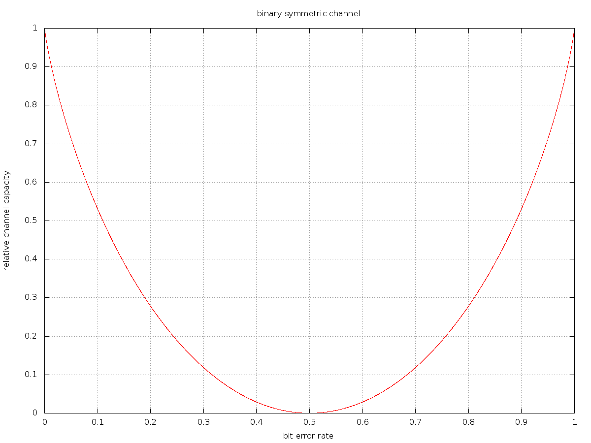
If you read the details on binary symmetric channels you might conclude that this does not apply to our case. After all DCF77 does not use a binary symmetric channel. And of course you are right. However this does not make things better. Asymmetric channels are harder to model but if you go through the math you will find that the DCF77 channel capacity is even lower. Even worse: the channel encoding for DCF77 is far from optimal. Thus in the presence of noise we will end up significantly below the theoretical limit.
The PTB experts were neither lazy nor stupid. At the time they invented their encoding scheme computational resources where expensive. Thus the channel was instead optimized for easy decoding. If you read through their documentation you will find out that they are actually very clever and already have a good solution. Unfortunately I did not find any cheap receiver for the improved transmission scheme. Hence I will stick to the old school signal.
Now what does this all mean? Well, it means that right now the standard decoding mechanism + filter tries to extract to much information from the signal. Each second the data (short pulse, long pulse, no pulse at all) is decoded. In addition phase information is retrieved. That is the start of the pulses is retrieved. If we assume that standard decoders try to capture the phase to about a tenth of a second we will find that they actually try to extract something around 4 bits per second. In the presence of noise this is definitely to much.
In order to deal with this we will now split the whole deconding process into pieces. The first step will be to capture the phase and nothing else. That is we want to find the starts of the 1s ticks and nothing else. So how much information is required to find those? The answer is “it depends” 😉 Suppose we would have a perfect precise clock. Then we could generate 1s ticks on our own. The only information we would need would the phase difference to the DCF77 signal. Once the signals would be in phase we would not need any additional information at all. So if we find a way to use the information contained in a longer sequence then we could decrease the average information required as much as we want.
Unfortunately we do not have a perfect local clock. Otherwise we would not need an external clock in the first place. However we have a pretty good local clock – the crystal of the Arduino.
Attention: there are Arduinos with only a resonator. Especially the most up to date model the Uno does not have a crystal. What I am going to implement needs a reasonable accurate local clock. If you want to repeat my experiment ensure that you get an Arduino with a crystal. Of course the Blinkenlighty has a crystal instead of a resonator.
The idea is to synchronize the local clock of the Arduino with the DCF77 signal. The point is that the phase is then synthesized by the Arduino. The only information that needs to be extracted from the signal is the phase difference. As it turns out this can be done by evaluating the signal during longer timer periods than just 1s intervalls. Thus we will extract significantly less information on average. The underlying mechanism is known as a phase detector. An implementation that uses a phase detector to sync a clock is also known as a phase locked loop.
Enough theory – here is the code.
//
//  www.blinkenlight.net
//
//  Copyright 2012 Udo Klein
//
//  This program is free software: you can redistribute it and/or modify
//  it under the terms of the GNU General Public License as published by
//  the Free Software Foundation, either version 3 of the License, or
//  (at your option) any later version.
//
//  This program is distributed in the hope that it will be useful,
//  but WITHOUT ANY WARRANTY; without even the implied warranty of
//  MERCHANTABILITY or FITNESS FOR A PARTICULAR PURPOSE. See the
//  GNU General Public License for more details.
//
//  You should have received a copy of the GNU General Public License
//  along with this program. If not, see http://www.gnu.org/licenses/


const uint8_t dcf77_sample_pin = 19; // A5
const uint8_t dcf77_analog_sample_pin = 5;
const uint8_t dcf77_monitor_pin = 18;
const uint8_t dcf77_synthetic_clock_pin = 17;

const uint8_t first_debug_pin = 5;


namespace DCF77_Demodulator {
    const uint8_t bin_count = 100;

    typedef struct {
        uint16_t data[bin_count];
        uint8_t tick;

        uint32_t noise_max;
        uint32_t max;
        uint8_t max_index;
    } phase_bins;

    phase_bins bins;

    const uint16_t samples_per_second = 1000;

    const uint16_t samples_per_bin = samples_per_second / bin_count;
    const uint16_t bins_per_10ms  = bin_count / 100;
    const uint16_t bins_per_50ms  =  5 * bins_per_10ms;
    const uint16_t bins_per_60ms  =  6 * bins_per_10ms;
    const uint16_t bins_per_100ms = 10 * bins_per_10ms;
    const uint16_t bins_per_200ms = 20 * bins_per_10ms;
    const uint16_t bins_per_500ms = 50 * bins_per_10ms;


    void setup() {
        for (uint8_t index = 0; index < bin_count; ++index) {
            bins.data[index] = 0;
        }
        bins.tick = 0;

        bins.max = 0;
        bins.max_index = 255;
        bins.noise_max = 0;
    }

    uint16_t wrap(const uint16_t value) {
        // faster modulo function which avoids division
        uint16_t result = value;
        while (result >= bin_count) {
            result-= bin_count;
        }
        return result;
    }

    void phase_detection() {
        // We will compute the integrals over 200ms.
        // The integrals is used to find the window of maximum signal strength.
        uint32_t integral = 0;

        for (uint16_t bin = 0; bin < bins_per_100ms; ++bin)  {
            integral += ((uint32_t)bins.data[bin])<<1;
        }

        for (uint16_t bin = bins_per_100ms; bin < bins_per_200ms; ++bin)  {
            integral += (uint32_t)bins.data[bin];
        }

        bins.max = 0;
        bins.max_index = 0;
        for (uint16_t bin = 0; bin < bin_count; ++bin) {
            if (integral > bins.max) {
                bins.max = integral;
                bins.max_index = bin;
            }

            integral -= (uint32_t)bins.data[bin]<<1;
            integral += (uint32_t)(bins.data[wrap(bin + bins_per_100ms)] + bins.data[wrap(bin + bins_per_200ms)]);
        }

        // max_index indicates the position of the 200ms second signal window.
        // Now how can we estimate the noise level? This is very tricky because
        // averaging has already happened to some extend.

        // The issue is that most of the undesired noise happens around the signal,
        // especially after high->low transitions. So as an approximation of the
        // noise I test with a phase shift of 200ms.
        bins.noise_max = 0;
        const uint16_t noise_index = wrap(bins.max_index + bins_per_200ms);

        for (uint16_t bin = 0; bin < bins_per_100ms; ++bin)  {
            bins.noise_max += ((uint32_t)bins.data[wrap(noise_index + bin)])<<1;
        }

        for (uint16_t bin = bins_per_100ms; bin < bins_per_200ms; ++bin)  {
            bins.noise_max += (uint32_t)bins.data[wrap(noise_index + bin)];
        }
    }

    void advance_tick() {
        if (bins.tick < bin_count - 1) {
            ++bins.tick;
        } else {
            bins.tick = 0;
        }
    }

    uint8_t phase_binning(const uint8_t input) {
        // how many seconds may be cummulated
        // this controls how slow the filter may be to follow a phase drift
        // N times the clock precision shall be smaller 1
        // clock 30 ppm => N < 300
        const uint16_t N = 300;

        advance_tick();

        if (input) {
            if (bins.data[bins.tick] < N) {
                ++bins.data[bins.tick];
            }
        } else {
            if (bins.data[bins.tick] > 0) {
                --bins.data[bins.tick];
            }
        }
        return bins.tick;
    }

    void detector_stage_2(const uint8_t input) {
        const uint8_t current_bin = bins.tick;

        const uint8_t threshold = 30;

        if (bins.max-bins.noise_max < threshold ||
            wrap(bin_count + current_bin - bins.max_index) == 53) {
            // Phase detection far enough out of phase from anything that
            // might consume runtime otherwise.
            phase_detection();
        }
    }

    void detector(const uint8_t sampled_data) {
        static uint8_t current_sample = 0;
        static uint8_t average = 0;

        // detector stage 0: average 10 samples (per bin)
        average += sampled_data;

        if (++current_sample >= samples_per_bin) {
            // once all samples for the current bin are captured the bin gets updated
            // that is each 10ms control is passed to stage 1
            const uint8_t input = (average> samples_per_bin/2);

            phase_binning(input);

            detector_stage_2(input);

            average = 0;
            current_sample = 0;
        }
    }

    void get_quality(uint32_t &lock_max, uint32_t &noise_max) {
        lock_max = bins.max;
        noise_max = bins.noise_max;
    }

    uint8_t get_time_value() {
        const uint8_t threshold = 2;

        return (bins.max-bins.noise_max >= threshold)? (bins.max_index + bins.tick + 1) % bin_count: -1;
    }

    uint8_t debug() {
        Serial.print(F("Phase: "));

        const bool uses_integrals = sizeof(bins.max) == 4;

        Serial.print(get_time_value(), HEX);
        Serial.print(F(" Tick: "));
        Serial.print(bins.tick);
        Serial.print(F(" Quality: "));
        Serial.print(bins.max, DEC);
        Serial.print('-');
        Serial.print(bins.noise_max, DEC);
        Serial.print(F(" Max Index: "));
        Serial.print(bins.max_index, DEC);
        Serial.print('>');

        for (uint8_t index = 0; index < bin_count; ++index) {
            if (index == bins.max_index ||
                (!uses_integrals && index == (bins.max_index+1) % bin_count) ||
                (uses_integrals && (index == (bins.max_index+10) % bin_count ||
                (index == (bins.max_index+20) % bin_count)))) {
                Serial.print('|');
                }
                Serial.print(bins.data[index],HEX);
        }
        Serial.println();
        return bins.max_index;
    }
}


void process_one_sample() {
    // The Blinkenlight LEDs will cut off the input signal
    // below a logical high. This is due to the weak
    // output signal of the DCF module.
    // Hence for the Blinkenlighty
    // and the Blinkenlight shield we can not use
    // digitalRead.

    // Comment the line below if you are not using this code with a
    // Blinkenlighty or Blinkenlight shield.
    const uint8_t sampled_data = analogRead(dcf77_analog_sample_pin)>200? 1: 0;
    // Uncomment the line below if you are using this code with a standard Arduino
    //const uint8_t sampled_data = digitalRead(dcf77_sample_pin);

    digitalWrite(dcf77_monitor_pin, sampled_data);

    DCF77_Demodulator::detector(sampled_data);
}

ISR(TIMER2_COMPA_vect) {
    process_one_sample();
}

void initTimer2() {
    // Timer 2 CTC mode, prescaler 64
    TCCR2B = (0<<WGM22) | (1<<CS22);
    TCCR2A = (1<<WGM21) | (0<<WGM20);

    // 249 + 1 == 250 == 250 000 / 1000 =  (16 000 000 / 64) / 1000
    OCR2A = 249;

    // enable Timer 2 interrupts
    TIMSK2 = (1<<OCIE2A);
}

void stopTimer0() {
    // ensure that the standard timer interrupts will not
    // mess with msTimer2
    TIMSK0 = 0;
}


void setup() {
    Serial.begin(115200);
    Serial.println();

    pinMode(dcf77_sample_pin, INPUT);
    digitalWrite(dcf77_sample_pin, HIGH);

    pinMode(dcf77_monitor_pin, OUTPUT);
    pinMode(dcf77_synthetic_clock_pin, OUTPUT);

    for (uint8_t pin = 0; pin<10; ++pin) {
        pinMode(first_debug_pin + pin, OUTPUT);
    }

    DCF77_Demodulator::setup();

    initTimer2();
    stopTimer0();
}

void loop() {
    using namespace DCF77_Demodulator;

    const uint8_t phase = debug();

    for (uint8_t pin = 0; pin<10; ++pin) {
        digitalWrite(first_debug_pin + pin, phase % 10 == pin);
    }
    digitalWrite(dcf77_synthetic_clock_pin, (bins.tick - phase + bin_count) % bin_count < bin_count / 10);
}
If you look at the code you will see 3 important features.
- The code samples at 1 kHz. That is one sample per millisecond. However it does not use the msTimer2 library.
- The code averages every 10 samples and put the result into “bins”.
- The code does not search sudden changes in the values of the bins. Instead it computes some sum that I called “integral” and searches for a maximum of this sum.
Lets start with the bins. The idea is as follows. If the signal would be in sync then each second (but the last of the minute) there would be a 100ms high signal. Then 100ms either high or low and then a 800ms low signal. This repeats every second (but the last of the minute). Even if the signal is not in sync I know that both the local clock and the DCF77 clock have a 1s period. Thus the signal I see at any specific time should be the same 1s earlier or later. Except for the last second of the minute and except for the second 100ms after the start of the second (relative to DCF77). Thus I introduced 100 bins that represent the averaged signal for 10ms time slots. Whenever the code has 10ms worth of samples it averages them and puts them into the current bin. Afterwards it will proceed to the next. After the last bin it will start over again.
The number of bins as well as the sample rate were not chosen by chance. More bins imply better resolution. With 100 bins my clock can have a resolution of 10ms. However more bins consume more memory. Since the Arduino has only 2k of Ram I stick with 100 bins (which consume 200 Bytes of memory). In addition the Arduino has only a 16 Mhz clock. So if I sample at 1kHz I will have only 16000 clock cycles per sample. This is not yet an issue but later stages of my clock will consume more cycles. So increasing the number of bins and the sample rate is a bad idea given the memory and the clock constraints. Additionaly there is not to much to gain by increasing the sample rate as most DCF77 receivers have a bandwidth well below 1 kHz.
So what I end up with is a set of bins with averages of the signal. Have a look at red graph in the plot below. The red graph represents the bins for 80% noise. I normalized them to the range of the initial signal. As you can see the noise brings everything closer to the average of 0.5. Still it has no significant issue with the noise.
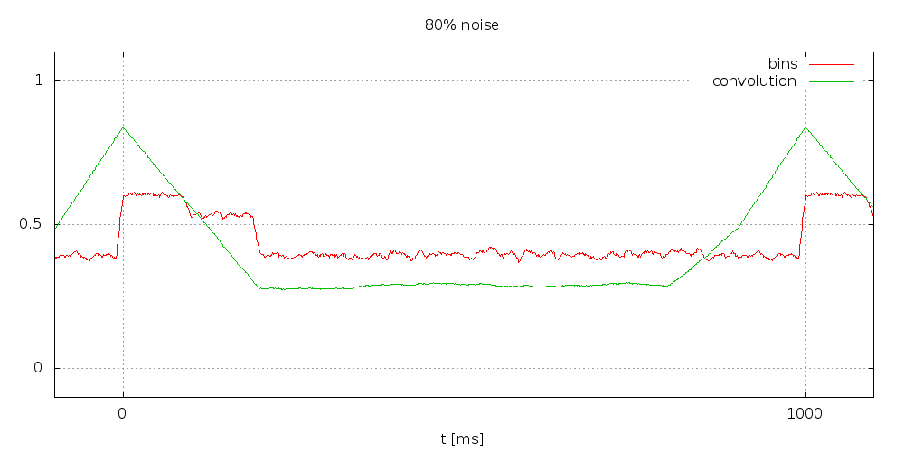
In the plot you can also see a green graph labeled “convolution”. This has very clean peaks at in sync with the phase. Now what is this? These are the “integrals” or sums that I compute during phase detection.
Now what is behind those integrals? Basically I want to correlate the binned signal with something that looks like the real signal. Notice that I know that the signal should be high for 100ms and low for 800ms but I do not know how it will behave between in the middle. Thus I will correlate with something that is 0 during the second 100ms.

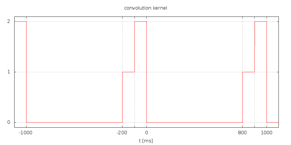
The next step is some simple mathmatical trickery and implementation optimization. First I will use convolution instead of correlation. This is almost the same. The only thing is I have to replace the kernel by a mirrored version of itself. There is nothing magic about this. It makes no difference for the implementation. However it makes theoretical analysis simpler because convolution is easier to deal with. In addition I translate the kernel up. That is I add 1 to it. Thus I need not deal with negative numbers anymore. This will translate convolution result up as well but it has no impact on the argument (place on the time/bin axis) of the maximum.
Below you find a picture of the convolution kernel.
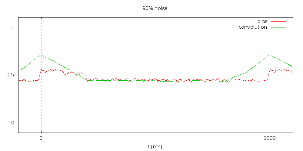
Quite a lot of effort. Will it pay of? Lets have a look at the simulation for higher noise levels (click to enlarge).
The simple exponential filter had no more chance at 90%. This is at a bit error rate of 45% or a theoretical channel capacity of about 0.72%. The convoluted bins still give a very clear indication of the phase.
At 95% noise things are still well under control.

Even 98% noise can still be handled by this detector. Notice that this is a bit error rate of 49%. Which in turn implies that the theoretical channel capacity is below 0.029%. About 25 times less than at 90% noise.

At 99% noise finally things start to get out of control though.

Now back to the magic number N=300. Why did I chose N=300 and not more (or less)? More would mean I average on more bins. This in turn would allow to achieve even more noise tolerance. However there is some limit imposed by the accuracy of the local clock. If the local clock deviates from DCF77 this has the same effect like an additional convolution with some rectangle pulse. The width of this pulse is the clock deviation during the sample period. So if N=300 and the clock is accurate to 30 ppm this pulse has a width of ~3000 microseconds or 9ms. This is slightly less than one bin. Below there is a plot of the impact of the clock deviation to a clean signal. That is I convoluted a clean signal with the convolution kernel and an additional rectangle pulse. The plots are for N=300. Increasing N by a factor of x is the same as increasing the clock deviation by a factor of x (and vice versa). Since the Blinkenlighty has a clock that is at least accurate to 30 ppm (actually it is a little bit better but I wanted to stay save) I settled for N=300.
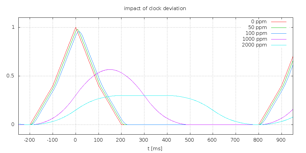
Also notice that resonator based Arduinos will have clock deviations beyond 1000 ppm. So the smoothest of the curves applies. With other words even without noise the detector will fail with those. As I already said this applies especially to the Arduino Uno.
This finally brings me back to the comment on msTimer2. The msTimer2 library has some very minuscule glitch that will make it very slightly slower than 1000 samples per second (less than 0.1%). Usually this is completely irrelevant but for the current purposes the deviation must be kept as small as possible. This was the reason I implemented the timer code on my own instead of using one of my favourite libraries.
Here is a video of the code in action. Notice that it uses the LEDs to visualize the phase at a resolution of 10ms, 1/100s. If you have a close look at the monitor LEDs you can see that the signal is somewhat noisy. Not very noisy but enough such that none of my commercial clocks will get a lock. Watch and see how fast and nicely it locks to the DCF77 phase and keeps it 🙂


Hi,
Very nice to get the theory and working example for a DCF77 receiver which can handle such noise! I am currently trying to build a DCF77 receiver using the arduino platform and will definitely come back to some aspects and ideas you mentioned!
What I dont get in this article is whether you still use the code from step 1 as input for your PLL or whether this new approach will completely replace the first step. I think that this is a complete replace because you cannot use the values after applying the Schmitt-Trigger here but this is only my current suggestion 😉
Or do you currently only try different approaches (your steps toward a new DCF77 decoder) to combine them later on to “one big” solution?
I am looking forward to the remaining work on the DCF77 decoder as this sounds very promising to me!
Best Regards,
Tobias
The exponential filter approach is a benchmark only. I combine this to a big solution,
Hi,
Compiled the code on arduino win 1.0.5, loaded to atmega328@16Mhz. The problem is phase_detection function takes 3.6ms to complete, but it has to finish in less than 1ms (before next interrupt). Do you have any idea why it takes so long?
Thank you for excellent work!.
Kind Regards,
Michał
Hi again,
I did the same as you described: “I just added two digital write statements around the interrupt processing to toggle a pin. The actual performance measurement was then performed with a DSO.” Please find link to the DSO screenshot: https://picasaweb.google.com/109682483922379219260/12Listopada2013?authuser=0&authkey=Gv1sRgCJeH_afHm_Gn0wE&feat=directlink
I looked it up what version of Arduino I am using: Arduino 1.0 on Ubuntu. Would you mind to compile my code with 1.0 and see if you still have the same issue? I definitely have no idea why it might take that long. Especially because with the subsequent experiments I add more and more computations for the signal processing stages and it stays below 1ms. Did you do any changes to my code besides the debug pin instrumentation?
My changes to your code:
void process_one_sample() {
…
const uint8_t sampled_data = !digitalRead(dcf77_sample_pin); //(I have inverted dcf77 output)
…
}
…
ISR(TIMER2_COMPA_vect) {
digitalWrite(16, HIGH);
process_one_sample();
digitalWrite(16, LOW);
}
…
void setup() {
…
pinMode(16, OUTPUT);
…
}
I’ve tried arduino 022, 1.0, 1.0.3, 1.0.5 for Windows, every time the same 3.6ms every 10th interrupt.
It looks like the loop:
for (uint16_t bin = 0; bin < bin_count; ++bin) {
…
}
causes the problem. After commenting out the loop interrupt time dropped to 340us.
The best way to see the problem is to reset arduino without dcf77 receiver connected, then the phase_detection is called for every bin.
Could you please check it on your arduino using DSO?
Could you please send me your hex code in case my Windows environment causes the problem.
BR,
Michał
Still don’t know why it doesn’t work on my arduino. I’ve compiled your code on NXP LPC1114 (cortex-m0 48MHz) using LPCExpresso 6. The result is phase decoder works very good (as far as I remember longest interrupt time takes about 300 us).
BR,
Michał
By now I upgraded to 1.5.5 –> my code stopped working. Then I downgraded to 1.0.1 –> it still did not work. I downgraded to 1.0 and it worked again. Hmmm. I have no clue what exactly is causing this issue. As soon as I find out I will tell you.
Finally I found a reason why it fails with some versions of Arduino. It seems that the newer versions include an old compiler version. Would you please set the compiler options to verbose and check the path to your compiler? Would you then call this compiler with option “–version”?
Did this issue resolve?
Yes, but what are you aiming at? Do you have troubles with the code? Did you read the compatibility section of the DCF77 Library that I linked in my last answer?
Sorry for not answering earlier with the HEX file. I had some issues with my system. But here it is:
:100000000C9476000C949E000C949E000C949E0020
:100010000C949E000C949E000C949E000C94FA028A
:100020000C949E000C949E000C949E000C949E00D8
:100030000C949E000C949E000C949E000C949E00C8
:100040000C9423070C949E000C94E1050C9412066A
:100050000C949E000C949E000C949E000C949E00A8
:100060000C949E000C949E00204D617820496E6493
:1000700065783A2000205175616C6974793A2000E6
:10008000205469636B3A200050686173653A200020
:1000900000000000240027002A00000000002500C6
:1000A00028002B0000000000230026002900040483
:1000B0000404040404040202020202020303030310
:1000C00003030102040810204080010204081020EC
:1000D00001020408102000000007000201000003D4
:1000E00004060000000000000000D70611241FBE17
:1000F000CFEFD8E0DEBFCDBF11E0A0E0B1E0E6E099
:10010000F0E102C005900D92A231B107D9F712E0DB
:10011000A2E1B1E001C01D92A639B107E1F710E0FC
:10012000CCEED0E004C02297FE010E94FD07CA3E3B
:10013000D107C9F70E9414070C9401080C94000021
:10014000E2E1F1E01192119281E0EA3DF807D1F786
:100150001092DA011092DF011092E0011092E10199
:100160001092E2018FEF8093E3011092DB01109275
:10017000DC011092DD011092DE0108959F92AF9292
:10018000BF92CF92DF92EF92FF920F931F93CF9384
:10019000DF93E2E1F1E0EF0180E090E0DC01299102
:1001A000399140E050E0220F331F441F551F820F4A
:1001B000931FA41FB51F21E0C632D20781F72991F2
:1001C000399140E050E0820F931FA41FB51F21E03A
:1001D000CA33D207A1F71092DF011092E00110920A
:1001E000E1011092E2011092E301AA24BB2465010F
:1001F00064E170E09924A816B906CA06DB0628F463
:100200004CEE942E960E5C016D01E190F1909B01F5
:100210002A50304002C02456304024363105D8F7E9
:10022000E901CC0FDD1FCE5EDE4F488159819B0175
:1002300002C02456304024363105D8F7E901CC0FEE
:10024000DD1FCE5EDE4F288139816F5F7F4F6837BB
:10025000710599F0240F351F40E050E000E010E0F8
:10026000EE0CFF1C001F111F2E193F09400B510BF4
:10027000820F931FA41FB51FBECFA092DF01B092C3
:10028000E001C092E101D092E2019092E301692D78
:1002900070E06C5E7F4F02C064567040643671053A
:1002A000D8F780E090E0DC01E0E0F0E09F01260F6D
:1002B000371F02C02456304024363105D8F7E901F3
:1002C000CC0FDD1FCE5EDE4F2881398140E050E04B
:1002D000220F331F441F551F820F931FA41FB51FEA
:1002E0003196EA30F10511F7EAE0F0E09F01260FC0
:1002F000371F02C02456304024363105D8F7E901B3
:10030000CC0FDD1FCE5EDE4F2881398140E050E00A
:10031000820F931FA41FB51F3196E431F10531F709
:100320008093DB019093DC01A093DD01B093DE01AB
:10033000DF91CF911F910F91FF90EF90DF90CF90C1
:10034000BF90AF909F9008958091DA01833620F49A
:100350008F5F8093DA0108951092DA010895DF9398
:10036000CF930F92CDB7DEB789830E94A401E091AD
:10037000DA018981882369F0F0E0EE0FFF1FEE5E5D
:10038000FE4F8081918121E08C32920770F40196BA
:100390000AC0F0E0EE0FFF1FEE5EFE4F80819181FC
:1003A000009719F00197918380838091DA010F9073
:1003B000CF91DF9108956091DA018091DF019091F2
:1003C000E001A091E101B091E2012091DB013091C7
:1003D000DC014091DD015091DE01821B930BA40BE7
:1003E000B50B8E319105A105B10588F0862F90E0FF
:1003F0008C599F4F2091E301821B910902C08456C2
:10040000904084369105D8F78533910511F40E9408
:10041000BE0008951F939091E401980F9093E4011A
:100420008091E5018F5F8093E5018A3070F011E0E3
:10043000963008F410E0812F0E94AF01812F0E94B6
:10044000DB011092E4011092E5011F910895809163
:10045000DF019091E001A091E101B091E2012091D2
:10046000DB013091DC014091DD015091DE01821B06
:10047000930BA40BB50B82309105A105B10568F073
:100480002091E3018091DA0190E0820F911D0196A5
:1004900064E670E00E94B20708958FEF0895EF922E
:1004A000FF920F931F93CF93DF938EE692E068E85D
:1004B00070E00E9470040E942702682F8EE692E08E
:1004C00040E150E00E9420058EE692E060E870E096
:1004D0000E9470048EE692E06091DA014AE050E0FA
:1004E0000E9420058EE692E065E770E00E947004AD
:1004F0004091DF015091E0016091E1017091E201D2
:100500008EE692E02AE030E00E940A058EE692E054
:100510006DE20E9493044091DB015091DC016091F7
:10052000DD017091DE018EE692E02AE030E00E946B
:100530000A058EE692E068E670E00E9470048EE69E
:1005400092E06091E3014AE050E00E9420058EE6CF
:1005500092E06EE30E94930402E111E0C0E0D0E07B
:10056000B4E6EB2EF12C2091E3012C1789F030E05A
:10057000C9010A96B7010E94B207C817D90741F00E
:10058000C9014496B7010E94B207C817D90729F4D8
:100590008EE692E06CE70E949304F80161917191FC
:1005A0008F018EE692E040E150E00E94190521960D
:1005B000C436D105C1F68EE692E00E949B0480917C
:1005C000E301DF91CF911F910F91FF90EF9008957C
:1005D0001F9385E00E94140411E0893C91050CF4FE
:1005E00010E082E1612F0E94DC03812F0E940A0249
:1005F0001F9108951F920F920FB60F9211242F93FF
:100600003F934F935F936F937F938F939F93AF939A
:10061000BF93EF93FF930E94E802FF91EF91BF9188
:10062000AF919F918F917F916F915F914F913F918A
:100630002F910F900FBE0F901F9018958CE0809314
:10064000B10082E08093B00099EF9093B300809363
:10065000700008951F938EE692E040E052EC61E056
:1006600070E00E9459068EE692E00E949B0483E1AE
:1006700060E00E94B80383E161E00E94DC0382E154
:1006800061E00E94B80381E161E00E94B80315E0D7
:10069000812F61E00E94B8031F5F1F30C9F70E94DD
:1006A000A0000E941E0310926E001F9108950F93E8
:1006B0001F93DF93CF930F92CDB7DEB70E944F0207
:1006C000182F6AE00E94A60700E0802F8B5F61E090
:1006D000901360E099830E94DC030F5F99810A30D8
:1006E000A1F72091DA0130E02C593F4F211B31094D
:1006F000C90164E670E00E94B20761E08A309105AA
:100700000CF060E081E10E94DC030F90CF91DF915B
:100710001F910F910895833071F0843028F4813057
:10072000A1F0823021F514C08630B1F08730D1F0CD
:100730008430E9F404C0809180008F7703C08091F9
:1007400080008F7D80938000089584B58F7702C0EC
:1007500084B58F7D84BD08958091B0008F7780939C
:10076000B00008958091B0008F7D8093B00008950F
:1007700090E0FC01EE53FF4F2491FC01E255FF4F46
:10078000E491EE23C1F0F0E0EE0FFF1FE057FF4FC2
:1007900085919491DC01662341F49FB7F8948C9184
:1007A000209582238C939FBF08959FB7F8948C91D6
:1007B000822B8C939FBF08950F931F93DF93CF934A
:1007C0000F92CDB7DEB7282F30E0F901EA52FF4F84
:1007D0008491F901EE53FF4F149122553F4FF901D7
:1007E00004910023D9F0882321F069830E948B03B0
:1007F0006981E02FF0E0EE0FFF1FE656FF4F859175
:100800009491DC019FB7F894662321F48C911095A4
:10081000812302C08C91812B8C939FBF0F90CF912D
:10082000DF911F910F9108958E3008F08E508770E0
:10083000909100019295990F990F907C982B90932D
:100840007C0080917A00806480937A0080917A00A5
:1008500086FDFCCF2091780030917900932F80E0C5
:1008600030E0282B392BC9010895CF92DF92EF9207
:10087000FF920F931F93CF93DF936C017B018A014B
:10088000C0E0D0E00FC0D7016D917D01D601ED91A0
:10089000FC910190F081E02DC6010995C80FD91F88
:1008A000015010400115110571F7CE01DF91CF9174
:1008B0001F910F91FF90EF90DF90CF900895DB0193
:1008C0000D900020E9F7AD0141505040461B570BF9
:1008D000DC01ED91FC910280F381E02D09950895F2
:1008E000EF92FF920F931F93CF93DF937C01062F1C
:1008F000172FC0E0D0E0F8010F5F1F4F649166230F
:1009000051F0F701A081B181ED91FC91C7010995EA
:10091000C80FD91FF0CFCE01DF91CF911F910F915A
:10092000FF90EF900895DC01ED91FC910190F08132
:10093000E02D099508950F931F93CF93DF93EC015A
:100940006DE00E9493048C01CE016AE00E94930442
:10095000080F191FC801DF91CF911F910F910895C2
:100960008F929F92AF92BF92CF92DF92EF92FF92BF
:100970000F931F93DF93CF93CDB7DEB7A1970FB639
:10098000F894DEBF0FBECDBF6C01042FE52FCB0165
:10099000122F19A2223008F41AE021E2E22EF12CE3
:1009A000EC0EFD1E812E9924AA24BB2403C0022F25
:1009B000E32FCA01602F7E2FA50194010E94C50775
:1009C000129F802D1124081B0894E108F1080A30B9
:1009D00014F4005D01C0095CF701008321153105A5
:1009E0004105510521F7C601B7010E945F04A19698
:1009F0000FB6F894DEBF0FBECDBFCF91DF911F9130
:100A00000F91FF90EF90DF90CF90BF90AF909F90AD
:100A10008F9008952115310549F4DC01ED91FC9189
:100A20000190F081E02D642F099508950E94B00493
:100A300008959A01AB0160E070E00E940A050895F4
:100A40009A01462F50E060E070E00E940A05089588
:100A5000FC0184859585FC01E05CFF4F208131819C
:100A60008E5B9F4FFC0180819181281B390B2F7376
:100A70003070C9010895FC0184859585FC01E05C16
:100A8000FF4F40815181FC01EE5BFF4F208131819E
:100A90004217530741F00190F081E02DE80FF91F54
:100AA000208130E002C02FEF3FEFC9010895FC0123
:100AB00084859585FC01E05CFF4F40815181FC01FC
:100AC000EE5BFF4F208131814217530771F0A08107
:100AD000B181A80FB91F2C918081918101968F73EC
:100AE00090709183808330E002C02FEF3FEFC90107
:100AF0000895DC011E968D919C911F97FC01E05C8E
:100B0000FF4F8E5B9F4F40815181DC012D913C91C5
:100B1000119742175307B9F708951F93FC01162F39
:100B200026853785D901A05CBF4F8D919C91019698
:100B300060E470E00E94B207D901AE5BBF4F4D91F7
:100B40005C91119784179507D1F3D901A05CBF4F31
:100B50000D90BC91A02DA20FB31F1C93A685B78545
:100B6000A05CBF4F11969C938E93A689B7892C9158
:100B700081E090E0058C02C0880F991F0A94E2F78B
:100B8000282B2C9381E090E01F910895FB01E05CFD
:100B9000FF4F208131812F5F3F4F2F733070DB017A
:100BA000AE5BBF4F4D915C9111972417350739F01B
:100BB000A081B181A60FB71F8C9331832083089544
:100BC00008951F920F920FB60F9211242F933F9307
:100BD0004F935F936F937F938F939F93AF93BF9345
:100BE000EF93FF938091C60066EE71E00E94C60508
:100BF000FF91EF91BF91AF919F918F917F916F91F5
:100C00005F914F913F912F910F900FBE0F901F90CA
:100C100018958EE692E00E942805009711F00E9438
:100C2000E00508951F920F920FB60F9211242F9393
:100C30003F935F936F937F938F939F93AF93BF93F4
:100C4000EF93FF9320916A0230916B0280916C02C6
:100C500090916D022817390731F48091C1008F7D82
:100C60008093C10016C0E0916C02F0916D02E65DC8
:100C7000FD4F208180916C0290916D02019660E49D
:100C800070E00E94B20790936D0280936C022093F3
:100C9000C600FF91EF91BF91AF919F918F917F918E
:100CA0006F915F913F912F910F900FBE0F901F900A
:100CB0001895DF92EF92FF920F931F93CF93DF93DC
:100CC000EC017A018B01DD24D394403081EE58078A
:100CD00080E0680780E0780749F4DD24EC89FD892D
:100CE000108260E874E88EE190E00FC0EC89FD8925
:100CF00081E090E00E8C02C0880F991F0A94E2F701
:100D0000808360E079E08DE390E0A80197010E9484
:100D1000C507215030404040504056954795379583
:100D2000279580E12030380710F0DD20B1F6E88902
:100D3000F9893083EA89FB892083EE89FF89408124
:100D400081E090E09C010A8C02C0220F331F0A94BC
:100D5000E2F7422B4083EE89FF8940819C010B8C96
:100D600002C0220F331F0A94E2F7422B4083EE8920
:100D7000FF8940819C010C8C02C0220F331F0A9412
:100D8000E2F7422B4083EE89FF8920810D8C02C05F
:100D9000880F991F0A94E2F7809582238083DF9160
:100DA000CF911F910F91FF90EF90DF9008951092D7
:100DB00071021092700288EE93E0A0E0B0E08093A0
:100DC000720290937302A0937402B0937502E0E7ED
:100DD000F2E085E091E09293829386EE91E0958730
:100DE00084878AE292E09787868785EC90E0918BF2
:100DF000808B84EC90E0938B828B80EC90E0958BE1
:100E0000848B81EC90E0978B868B86EC90E0918FC1
:100E1000808F84E0828F83E0838F87E0848F85E0FA
:100E2000858F81E0868F0895CF93DF930E946B07B3
:100E30000E942A03C9E0D6E00E9457032097E1F3FD
:100E40000E940906F9CF1F920F920FB60F9211243C
:100E50002F933F938F939F93AF93BF938091910272
:100E600090919202A0919302B091940230919502D8
:100E70000196A11DB11D232F2D5F2D3720F02D5779
:100E80000196A11DB11D209395028093910290932C
:100E90009202A0939302B093940280918D0290915C
:100EA0008E02A0918F02B09190020196A11DB11DFA
:100EB00080938D0290938E02A0938F02B093900244
:100EC000BF91AF919F918F913F912F910F900FBE46
:100ED0000F901F901895789484B5826084BD84B576
:100EE000816084BD85B5826085BD85B5816085BD25
:100EF000EEE6F0E0808181608083E1E8F0E010823E
:100F0000808182608083808181608083E0E8F0E07E
:100F1000808181608083E1EBF0E080818460808368
:100F2000E0EBF0E0808181608083EAE7F0E080819F
:100F300084608083808182608083808181608083FF
:100F40008081806880831092C1000895991B79E0A8
:100F500004C0991F961708F0961B881F7A95C9F749
:100F60008095089597FB092E07260AD077FD04D0B7
:100F70002ED006D000201AF4709561957F4F089509
:100F8000F6F7909581959F4F0895A1E21A2EAA1B1E
:100F9000BB1BFD010DC0AA1FBB1FEE1FFF1FA21729
:100FA000B307E407F50720F0A21BB30BE40BF50B26
:100FB000661F771F881F991F1A9469F760957095AF
:100FC000809590959B01AC01BD01CF010895AA1BAE
:100FD000BB1B51E107C0AA1FBB1FA617B70710F024
:100FE000A61BB70B881F991F5A95A9F78095909556
:100FF000BC01CD010895EE0FFF1F0590F491E02D87
:061000000994F894FFCFF3
:1010060001000000008D053504280557053B0579CC
:021016000500D3
:00000001FF
Thanks for an incredible blog and amazing DCF library. I have learnt a lot just by reading through the code and trying out the experiments. I am using a Conrad module in central London where the background noise level is very high.
I have one question: In the initTimer2() function you select a prescaler of 64 by setting bit CS22, and CTC mode by setting both WGM21 and WGM22. However according to my copy of the AT328P datasheet, CTC mode is enabled by setting bit WGM21 only. if WGM22 is also set then the mode is “Reserved”.
All the best, Ian
Great blog, did the Arduino incompatibility ever resolve.
Which incompatibility? For a list of all known issues look here: DCF77 Library
Hi Udo
I am experimenting with the MSF 60kHz signal here in England under noisy conditions and was about to give up until I saw some of your experiments. I captured the MSF signal at averaged 10mS buckets and then applied your convolution algorithm and seem to be able to recover phase to within a few bins.
The MSF signal is 100ms ON and then 100ms ON or OFF (A-bit) and 100ms ON or OFF (B-bit) and then 700ms off or 500ms ON and 500ms OFF for Minute Marker.
Your convolution is 100mS x 2+ next 100mS x1. Would the same be appropriate for MSF?
Thanks
Gavin
Hi Gavin,
I would suggest to convolute for 100 ms * 2 and 200 ms * 1. The existing kernel would also work but the one I suggest should yield slightly better results. Most probably you will not notice the difference though.
You might want to team up with “aido”. He created a MSF fork on github: https://github.com/aido/RadioClock/network
Hope that helps,
Udo
As an alternative to buying Udo’s processor board (e.g. if you need more USB capability than the FTDI chip provides) you might find this hack useful to get a crystal controlled Arduino UNO
The clock library runs really well on this for me. Thanks Udo.
http://www.castlewoodconsultants.com/Misc/ArduinosForDCF.pdf
Feel free to ask if anything is unclear
John Prentice
Hi Udo,
1) i think that your kernel model is a little wrong, It seems that you’ve forgotten than we accumulate in-signal, so 100 – 200 ms level isn’t simple 0.5 of 0 – 100 ms level. If probability of 0 and 1 bits are equal (= 1/2) then the 100 – 200 ms level is (slowly) grows to upper limit (300 in your code) . Practically we can see that this level is near 0 (it suggest than zeros are more frequent?) – any way, “0.5” seams not right.
2) In my test, I noticed that max level area (0..100 ms) gets wider after some time – I try more aggressive bins averaging – to subtract 2 where signal is 0 – this improves correlation result
thanks for the very good articles
/kris jaxa
Hi Jaxa,
yes, you are absolutely right. And I know this for quite a while. However I have not yet attacked this issue because it was good enough for me so far. The challenges are as follows:
1) If the signal fades, what happens to the receiver output. Is it biased to 0 or to 1? I have seen both ways.
2) For the slower changing parts of the signal (e.g. years), the change rate of the bits is much slower than the bandwidth of the filter. So even if it is statistically correct I will bias in the wrong direction a lot of thje time.
To fix this more parametrization and more sophisticated model are needed.
Hence I just use the most blunt approach and looked how far I can get.
Another thing that could be factored in: at this time I do not use the information that might be gathered during the 800 ms with full carrier. I could use this to determine if the reception conditions are currently good or bad. Also the Kernel is only properly matched to the sender side. Usually receivers have some low pass effect. Hence an optimal Kernel would also factor in the receiver behaviour. This results in slightly different period length. Would also be interesting.
In the end the whole library was some practice in signal processing. Thus I doubt that I will find the time to fix this any time soon.
But nevertheless, great insight.
Best regards, Udo
Hi Udo.
Thanks for your fantastic filter (sorry for my bat English… i’m Italian).
I have a problem with your filter (works on an Arduino uno Atmega328 with 16 Mhz crystal modification):
I look filter locks signal in few times but… the first bits in the filter synthetized output (the reserved meteo bits), have a wrong, time duration.
For example i measure an “1” bit comes from 170ms to 260ms, a “0” bit, from 55 to 160 msecs.
This “only” for the first 15-16 bits in an dcf77 frame, all the others are simply perfects!
Hy this? What i wrong?
Is there a modification on your filter to avoid this problem?
Thanks!!!
Hi Rodolfo,
this is correct behaviour. The superfilter is not really a filter. Actually it is a dcf77 clock followed by a synthesizer. Because the meteo stuff is encrypted I can not synthesize it. Hence I can do just a little bit of “grooming”. All other bits are synthesized. Hence the other bits are 100% spot on. For the meteo time I could do this if I would implement the meteo chiffre. Unfortunately it is proprietary. Still I know how to do this but I do not know what the legal implications are. So unless someone would be willing to sponsor the legal clarification I will not implement this.
Best regards,
Udo
tnx Udo.