
My DCF77 experiments were motivated by some discussion in the Arduino forum. Some members complained that they do not get reliable results with “standard” receivers although they are reasonable close to the radio station. As it turns out the receivers are not to blame but the software decoders. During my research in the internet I found no decoders that can reliably decode under noisy conditions.
But lets start at the beginning. What is DCF77 and what is it good for? DCF77 is a long wave radio signal that transmits the official time for Germany. The signal is provided by the Physikalisch Technische Bundesanstalt. Of course you can find excellent documentation on their web page.
Another very helpful page for any uncertainties about the signal is www.dcf77logs.de. This page has lots of logs and the corresponding decoded time. Thus it can be used to look up the signal for special events like timezone changes.
The DCF77 Code
The signal follows a very simple scheme. The carrier is a 77.5kHz signal. Such low frequencies are not easily obstructed by buildings. Hence the signal can be received almost everywhere (in Germany). This is a clear differentiator from e.g. GPS.
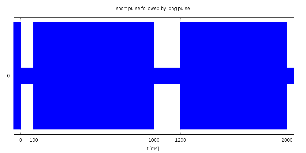
Each second starts with either a 100 ms or 200 ms high period followed by a low period of 900 ms or 800 ms. I call them short and long tick respectively. The short tick encodes a 0 bit, the long tick encodes a 1 bit.
This holds true for all seconds but the last second of a minute. The last second of a minute is always a 1000 ms low period. This is also known as “the sync mark”. Please keep attention that the sync mark is not the 60th second but the last second of each minute. This was introduced by the PTB to deal with so called leap seconds. The details behind leap seconds have theoretical and practical ramifications that lead to large controversies and technical complications far beyond one might imagine. If you do not want to read it up – the short summary is: leap seconds are to minutes as what leap days are to years. Unlike leap days leap seconds can not be predicted for more than ~6 months into the future. The practical consequence is that it introduces some undesirable uncertainity which impedes clock decoding somewhat. XKCD illustrates this in a funny way straight to the point. If you prefer precision instead of fun, the guys at the IERS have the final word.

DCF77 Code
The bits with their meanings are outlined in the diagram above. The details can be found on the PTB page or at Wikipedia.
The data bits contain wheather data that I do not care about. If you want to learn more about it the best starting point I found so far is here. Actually I also found an “endpoint”. Someone released the encryption scheme for the protocoll together with the key. You can find it with the well known web search engines. Since distribution of this key might be illegal I will not post it though.
Noise
Since the carrier frequency is so low the bandwidth is very limited. In addition this 77.5 kHz signal served/serves as a reference for precision clocks. Hence the PTB does not use a 100% modulation. Instead the signal gets amplitude modulated with only 25% modulation.
A 100% amplitude indicates a low (logical 0) a 75% 15% amplitude indicates a high (logical 1). This is to help the precision clocks to keep phase locks on the 77.5 kHz carrier signal. The downside is that the same scheme that helps to keep the phase locks makes the modulated data much more susceptible to noise. It picks up almost everything. For example my washing machine and my tumbler create enough low frequency noise such that no commercial clock within 10m can decode the time during their operation. Since 77.5kHz = 5 * 15.5 kHz even MP3 players can distort this signal. They can even spoof it. See here for the details.

short pulse followed by long pulse
The picture above exhibits a short pulse (indicating a 0 bit) and a long pulse (indicating a 1 bit ). The picture below exhibits the resulting 77.5 kHz signal with 85% modulation.
DCF77 amplitude modulation
A lot of people complain about the poor quality of some of the demodulator modules. However most fail to notice that the atainable accurarcy for the timing correlates with the bandwidth. Larger bandwidth allows for better accuracy. Unfortunately it also will pick up more noise. So before you think a particular module is crap, have a look at the bandwidth and think about low pass filtering the results.
There are many ways to deal with noise. One way would be to improve the antenna gain (that is: use a larger antenna) and in addition to shield it from noise. An example for such an approach is found here. Also notice that DCF77 antennas are directional, so turning the antenna in the proper direction will also help. The proper direction is perpendicular to the transmitter. The broadside must face in the direction of the transmitter.
Another way to deal with the noise is to apply (digital) filtering. This is the route I will follow. If you want to understand in depth what I am going to do I strongly recommend the book Digital Signal Processing. A Practical Guide for Engineers and Scientists by Steven Smith. I also found Information Theory, Inference, and Learning Algorithms by David MacKay very inspiring. I consulted the first book to learn more about filters and the second to learn more about error correction. A word of warning though: if you have no knowledge of higher mathmatics this is not exactly an easy read 😉
Low Pass Filtering
One of the simplest means for noise supression is a low pass filter. The idea is that most of the noise spectrum consists of “spikes” and other high frequency components. Supressing those should improve the decoded signal. My first DCF77 binary clock experiment utilizes a so called exponential filter to achieve this.
Matched Filtering
The best way to get rid of noise is of course by “cheating”. That is: if the signal is known in advance then there is nothing to decode. The only thing that remains is to determine the phase of the signal. With other words: the received signal is matched against an already known wave form. Since the DCF77 code is highly repetitive this allows to narrow down the effective bandwidth to almost zero. This kind of approach is also known as matched filter. Of course you can find it in the book Digital Signal Processing. A Practical Guide for Engineers and Scientists by Steven Smith. For any known signal the corresponding matched filter is actually the best possible linear filter that maximizes the signal to noise ratio.
Matched filtering is harder to implement than simple low pass filters. However it provides the best possible filter. My take on matched filtering is a dedicated DCF77 library. Its noise tolerances is significantly better than the simple low pass filter. According to theory it should be infintely better. However due to physical constraints (accuracy of the local clock) it is only about 100-1000 times more noise tolerant. Still you have to try it to believe it. This clock implementation can lock to a signal at noise levels where you would not expect any reasonable output at all. Depending on the noise level it may take up to an hour to get a phase lock. But then it faithfully decodes the time although the signal seems to be completely flooded with noise.


Hello, as you mentioned the matched filter, you can try it out practically with a simulator (http://www.grauonline.de/alexwww/ardumower/filter/filter.html). You can define your own signals there. Maybe it’s a good start to understand the matched filter 🙂
Hallo,
Gibt es Pläne die DCF77 Bibliothek auf einem ESP8266 (z.B. ESP-12E, NodeMCU 1.0) laufen zu lassen?
Viele Grüße
Karl-Heinz Volk
Von meiner Seite nicht. Müsste schon jemand anders bauen. Nur warum sollte man das tun? ESP und Freunde haben WLAN. Da kann man auch gleich einen NTP Client nehmen.
Hallo,
die hier dargestellte Amplitudenmodulation von 100 % auf 75 % ist so nicht richtig. Tatsächlich war früher die Trägerabsenkung nicht um 25 % sondern auf 25 % der vollen Amplitude. Seit über zehn Jahren wird auf 15 % der vollen Amplitude abgesenkt. So steht’s geschrieben z.B. in den PTB-Mitteilungen 118(2008), Heft 3.
Viele Grüße
Klaus Katzmann
Der Code für den DCF77 Generator ist jetzt korrigiert. Der Text und die Bilder kommen jetzt dran. Und nochmals vielen Dank für den Hinweis.
Hi
I can’t find the new code with the correction ?
Which correction do you refer to? In general you will find the most up to date code in my github repository here: https://github.com/udoklein/dcf77
You always find the most up to date code in my public repostory here: https://github.com/udoklein/dcf77
Hi again
I’m looking for the updated DCF77 Generator code.
Else tnx for all the good DCF stof
Hello, is this forum still active?
i am trying to build a DCF clock but most sites with info are dead for years.
i tried to order a HKW581 chip but all i did was loosing money.
anyone that can lead me?
thanks, Wim