
This experiment is a slight but very useful variation of my supply voltage measurement experiment. If the arduino is connected to USB the supply voltage is obviously close to the USB bus voltage. Hence the Arduino can be used to monitor the USB bus voltage. As it turns out this is more useful than expected. While testing the code I found a defective USB power supply. Now after more than 6 months of struggling with “flaky” USB devices I finally found the issue 🙂
You can run this experiment without the Blinkenlight Shield by setting debug to true. However without the display this is only half as useful. With the shield it has a standalone display.
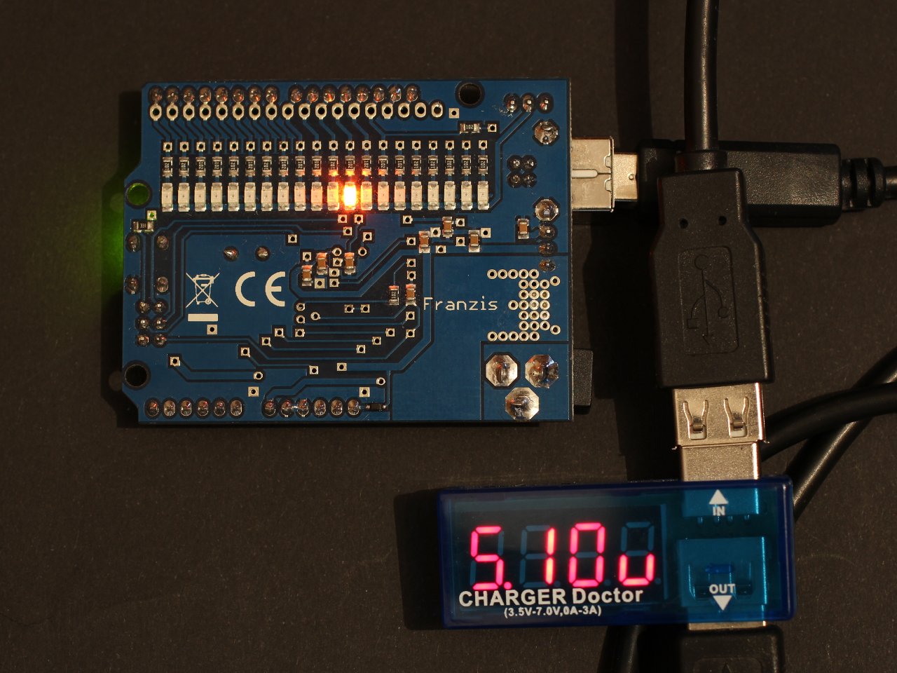
USB Voltage Monitor
As you can see from the picture I can check with one glance if one of the middle LEDs is lit. Thus I can see immediately if USB voltage is good or bad.
The code is pretty straightforward. I reuse the measurement part of the supply voltage measurement experiment and map the results to the 20 LEDs of the Blinkenlight shield. LED 0 will light up at 4 V or lower, Then every 0.1 V I light up the next LED. If the measured voltage is outside the USB spec the LED will blink. If it is inside the spec the LED will be constantly on. Thus I can very USB voltage compliance at a glimpse.
//
//  www.blinkenlight.net
//
//  Copyright 2014 Udo Klein
//
//  This program is free software: you can redistribute it and/or modify
//  it under the terms of the GNU General Public License as published by
//  the Free Software Foundation, either version 3 of the License, or
//  (at your option) any later version.
//
//  This program is distributed in the hope that it will be useful,
//  but WITHOUT ANY WARRANTY; without even the implied warranty of
//  MERCHANTABILITY or FITNESS FOR A PARTICULAR PURPOSE. See the
//  GNU General Public License for more details.
//
//  You should have received a copy of the GNU General Public License
//  along with this program. If not, see http://www.gnu.org/licenses/


const bool debug = false;

long read_vin_mv() {
    // data sheet 24.9.1 ADC Multiplexer Selection Register
    ADMUX = (1<<REFS0) | (1<<MUX3) | (1<<MUX2) | (1<<MUX1);
   // wait for adc to settle
    delay(5);

    // trigger conversion
    ADCSRA |= 1<<ADSC;

    // wait for conversion to finish
    while (ADCSRA & (1<<ADSC)) {};

    // read result
    uint16_t adc;
    adc = ADCL;
    adc |= ADCH<<8;

    // data sheet 24.7 ADC Conversion Result
    // ADC = vref * 1024 / vin
    // notice that vin and vref have exchanged roles because we
    // measure the reference voltage against vin
    // ==> vin [V] = vref [V] * 1024 / adc
    // ==> vin [mV] = 1.1 * 1000 * 1024 / adc
    return 1126400L / adc;
}

void setup() {
    if (debug) {
        Serial.begin(115200);
    }

    for (uint8_t led= debug? 2: 0 ; led<20; ++led) {
        pinMode(led, OUTPUT);
    }
}

void display(const uint8_t n, const bool alert) {
    static uint32_t ms = millis();
    static bool toggle = true;

    if (alert) {
        if (millis()-ms > 300) {
            ms = millis();
            toggle = !toggle;
        }
    } else {
        ms = millis();
    }

    for (uint8_t led= debug? 2: 0 ; led<20; ++led) {
        digitalWrite(led, (led==n) && toggle);
    }
}

void loop() {
    const uint16_t vin  = read_vin_mv();
    const uint16_t vmin = 4750;
    const uint16_t vmax = 5250;

    if (debug) {
        Serial.println(vin, DEC);
    }

    // map 4V to LED 0, 5.9V to LED 19.

    const bool alert = vin > vmax || vin < vmin;
    const uint8_t n = min(max((vin - 4000)/100, 0), 19);
    display(n, alert);
}
The measurement code in read_vin_mv is the same as in the supply voltage measurement experiment. However this time I map the result to the 20 LEDs of the shield. I also added some simple alert flag that makes the display blink in case the voltage is out of the admissible range. The important part is that the blink code will not block. Instead it stores the last time of a transition. Each time the blink code is processed it will check how much time has elapsed. If enough time has elapsed it will switch toggle again and remember the ms value for the next phase.
Pretty simple but very useful. In the Video you can see the reaction to proper and out of spec USB voltages. As soon as the USB voltage goes out of spec the lit LED will be out of the middle and it will start to blink.

