
After I have established one of the most noise tolerant software decoders for the DCF77 signal. I now focus on capturing a better signal, or even more important, a signal at all. Although my clock can deal with very poor signal noise ratios there must be at least some signal for it to do its work.
In order to improve on this side I followed two lines of investigation.
1) Learn about better Antenna design.
2) Evaluate different receiver boards.
With regard to the Antenna design I worked through the following three books.
Das neue Magnetantennenbuch: Selbstbau-Loops für Sende- und Empfangsbetrieb
Außergewöhnliche Empfangsantennen und ihre Anpassung für den Längst- und Kurzwellenbereich
The conclusions are:
(a) Bigger Antennas will result in better performance. That is they will offer more gain. In addition they can be created with a stronger directional characteristic. This in turn allows to improve signal noise ration in case the source of the noise is in a different direction than the DCF77 transmitter.
(b) Since it is technically almost impossible to have an antenna that has at least 1/4 of the wavelength of DCF77 (3868m/4 = 967m) a “small” antenna must be used. The typical solution is a resonant “magnetic” antenna. Since tuning is not completely trivial I decided to buy the biggest manufactured DCF77 antenna within my budget.
If you want to go for some really good antennas that are slightly above my budget have a look at the homepage of BAZ Spezialantennen. These Antennas are expensive but most probably worth the money. I did not try them though since my software solution did not require this at all.
With regard to different receiver modules I ordered modules from different “amateur” sources (Conrad, Reichelt and Pollin) and one “professional source” (HKW Elektronik). Here are the result of my completely unscientific benchmark.
Initially I started my experiments with a module from Conrad.
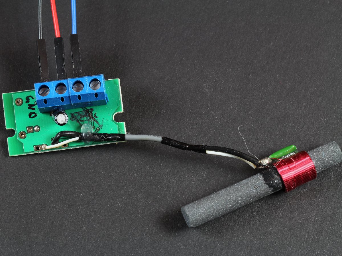
Conrad Module Top View
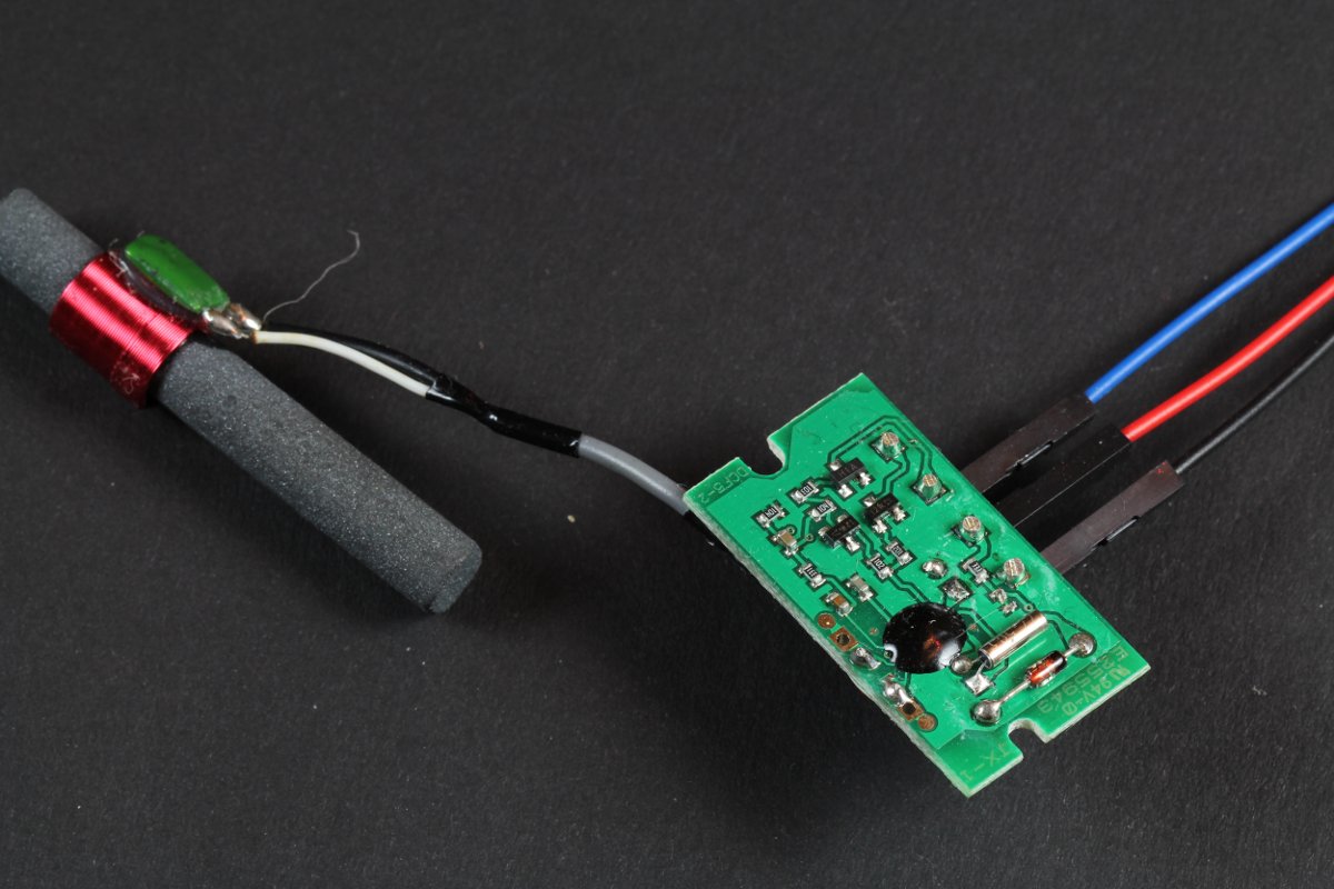
Conrad Module Bottom View
This module comes with a tuned (resonant) ferrite antenna (notice the green capacitor glued to the antenna). It also is very nice for prototyping as the leads can be attached with screws. In addition it offers a wide supply voltage range and two open collector outputs (one inverted).
The reception quality is sufficient for my clock but it was bad enough to get me started in advanced denoising techniques. It will pick up noise if my washing machnine or dryer are running.
The next module I ordered was from Reichelt.
Reichelt Module Top View
Reichelt Module Bottom View
It also has a tuned antenna. However the capacitor is an smd capacitor soldered on the board. This makes replacing the antenna slightly trickier. I can not say very much about the performance of this board because it failed during the first test. Since I did not like the antenna design anyway I did not reorder a second module.
I also ordered a very cheap module from Pollin since some people claim it is superior in performance to the Conrad board.
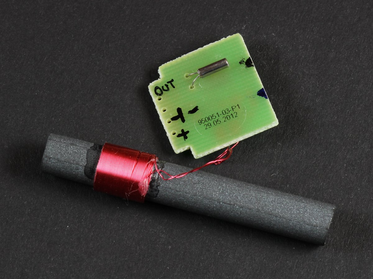
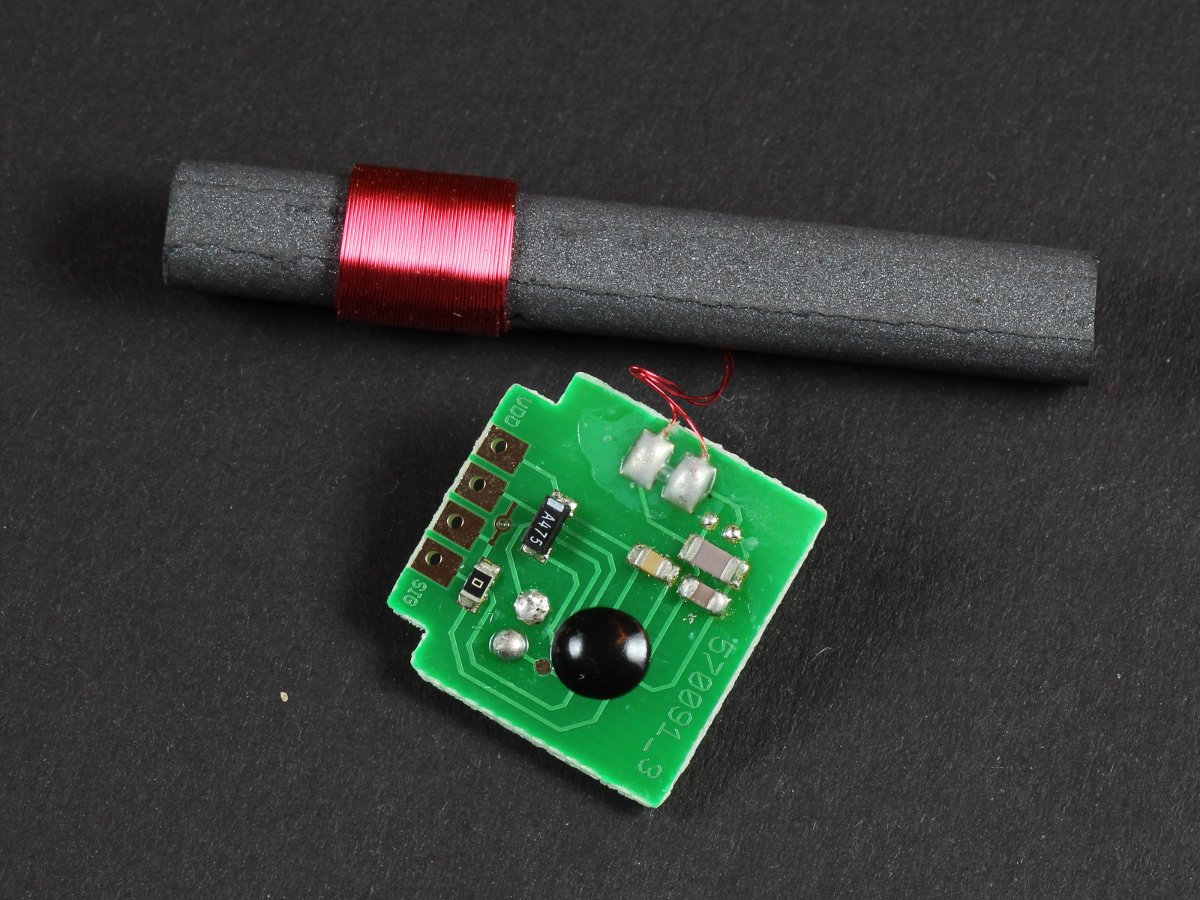
Pollin Module Top View
Pollin Module Bottom View
As the Conrad module it comes with a tuned antenna. The overall quality impression is slightly better as for the Conrad module. However it only supports a smaller voltage range and only one output. The washing machine and dryer tests showed similar results. So I did not find any significant differences in performance.
My conclusion so far is that the Conrad module is better suited for prototyping while the Pollin module is better suited for a fixed (=soldered) board.
Then I ordered a “professional module” from HKW. HKW offers lots of different modules and several different choices of antennas. I ordered one of the dumbest module they offer.
HKW Module Top View
HKW Module Bottom View
In addition I ordered all possible antenna choices.
HKW Antenna Choices
All antennas are tuned antennas. The smallest antenna is comparable in size to the antennas of the Conrad/Reichelt/Pollin modules. However it has a beefier feel and seems to be somewhat more precise tuned. The larger antennas are comparable in appearance to the Pollin module’s antenna. Since I did not want to try all variations I immediately started to test with the largest antenna. This is of course an unfair advantage. As expected this combination blows all of the other tested modules completely out of the water. I do not know if this is due to the antenna size alone or also due to the build quality of the module. However this combination is completely unaffected by the washing machine and/or dryer. It also is completely unsensitive to the placement in my flat. The other modules can not pick up a signal everywhere. This combination can. It is so good that I decided to not experiment with any combination any further.
The only issue is that HKW does not sell to end consumers. I assume that other “professional” modules show similar performance. My conclusion is: for superior performance try to get hold of a professional module that sports a 10 cm antenna.
I extracted the following data from the different module’s datasheets. I have no means to verify most of the values due to lack of measurement equipment. But the values all look somewhat reasonable.
| Conrad | HKW | Pollin | Reichelt | |
|---|---|---|---|---|
| Voltage [V] | 1.2 – 15 | 3 – 12 | 1.2 – 3 | 1.2 – 5 |
| Voltage typ. [V] | 3 – 12 | 3 | 1.2-5 | |
| Voltage max [V] | 15 | 12 | 3.5 | 5 |
| Current [uA] | <200 | <90 | <100 | |
| Current max [uA] | 200 | 120 | ||
| Output Type | sink | sink | sink/source | sink/source |
| Demodulated signal | inverted and none inverted | none inverted | inverted | inverted |
| Output Current max | 2 mA | 5 uA | 5 uA | |
| Bandwidth (Antenna) [Hz] | 700 | 600 | ||
| Temperature [C] | 00 – +50 | -40 – +85 | -10 – +70 | |
| Sensitivity [uV/m] | 25 (FTD02011R) | 80 | 50 | |
| Sensitivity [uV] | 0.4 – 0.6 | 1 |
The HKW antenna comparison is based on the HKW datasheets. Notice that they do not really state how “output” is measured. So this can be only used to compare HKW antennas with other HKW antennas. However it clearly shows how size affects antenna performance.
| Size [mm] | 10 x 40 | 10 x 60 | 10 x 100 |
|---|---|---|---|
| Bandwidth [Hz] | 700 | 700 | 700 |
| Output [mV] | 43.473 | 63.658 | 96.836 |
| Inductivity [uH] | 897 | 897 | 897 |
Final conclusion: size matters – bigger is better 😉


Have u ever considered building your own dcf77 receivers? The HKW modules seem to be professional and reliable. Does anyone know an end-user source for them?
Yes and no. Maybe I will once create one. However I doubt that it is easy to beat the professional modules like those from HKW. If I ever will built a receiver it has to outperform what you can buy. That is either I would combine an OCXO or DOCXO with SDR just because nobody did it that way so far. However this is a somewhat pointless exercise except for learning. If you need ***really*** accurate timing go to *bay and buy a used Trimble Thunderbolt. For ~100 Euros those are impossible to beat. My goal here was to achieve significant SNR improvements with relatively simple hardware.
With regard to the moduels: the HKW is definitely superior. However my software will compensate almost any crap, to you can go for the cheap modules. As long as they pick up just something it is probably good enough for my code.
Hi Udo,
Here is a DSP based DCF77 receiver project: http://www.marvellconsultants.co.uk/DCF/
Cool project. Although it has a different focus (precision instead of noise tolerance) I will look a little bit into the details. I am especially curious about their active antenna. Seems these guys know what they are doings. Thanks for pointing this out to me.
Hi Udo,
Awesome project. Been reading over the project hoping to implement an Arduino clock project but using a WWVB module instead. I hope you don’t mind if I ask you some questions.
I’m still a little confused about how you’re initially obtaining the signal from your DCF77 module (how did you determine the bandwidth – I don’t generally see this in the spec sheets? Does your implementation work equally well on modules with lower bandwidth?). If pull-up/pull-down resistors are present, is just using a digital input pin sufficient or does your implementation require analog sampling of voltages?
The only WWVB module that is currently available for the US seems to be from the UK – http://www.pvelectronics.co.uk/rftime/SYM-RFT-XX.pdf). From what I can understand, these modules basically output a high or low signal (sometimes inverted, such as this one). Does it even matter if the modules are for DCF77 or WWVB, or is the only difference due to the capacitor on the antenna that tunes them to 60KHz or 77KHz?
Also from what I can tell, they basically demodulate the AM stuff (and do nothing whatsoever with the phase info), and all of the work you describe is about processing (filtering, smoothing, low-pass, convolution, etc.) then using the cleaned up signal to derive phase information in your code and locking on to that, correct? So basically, the only difference I have to account for is likely the difference between DCF77 & WWVB time code decoding.
Sorry for the questions, but I’m new to Arduino (have so far gotten the RTC & LCD stuff to work, and now in the phase of finding a suitable WWVB antenna to hopefully start some testing). Please let me know if my understanding is incorrect, and obviously, any advice and pointers you can shed is greatly appreciated. If I can get this to work, I’ll write up my experience and point back to your project, of course.
Thanks,
Shane
Hi Shane,
I did not measure the bandwidth, I got it directly from the spec sheets. My implementation works of course well with lower bandwidth. Most commercial stand alone modules have a bandwidth of 100-500 Hz and my design is OK with them.
Digital pins are always sufficient. However the code was supposed to run with a Blinkenlight Shield / Blinkenlighty. Since those put additional load on the module’s output (and the modules are usually poor current sources) I have to analog sample them. If you have no additional load (e.g. plain Arduino + pullup) or if you have an additional driver you can sample with a digital pin. Most modules are designed to work with pullups.
The WWVB module you linked should be fine. However WWVB code is slightly different so you will need to adapt my decoder stages accordingly.
The WWVB module is a stupid decoder (similar to the DCF77 modules I used). That is it only demodulates the AM and outputs the demodulated signals. This is what my decoder approach needs. “Smart” modules already do to much behind the scenes and will NOT benefit from my approach. The difference between the modules is of course the tuning capacitor. However they usually also have different crystals. So you can not trivially repurpose a DCF77 module to WWVB. If you try you would need at least a suitable cap and a suitable crystal. In case of “dumb” modules this might suffice. If you try this let me know if it actually does. In case of smart modules it most probably will not work though.
The stuff I describe are basically two approaches. The first DCF77 (aka binary clock) was about low pass filtering. Although it is already superior to most other open implementations it is only intended as a benchmark. The rest of the work is about pushing it as close to the Shannon Limit as possible. As you properly remarked this is not done be decoding the signal. Instead I exploit that I know the whole signal in advance. (It is counting the time one second per step, right?) Thus I do not need to decode it. I just phase lock to it. So the only thing that I need to determine is the phase difference of the pre-known signal to the received signal and presto – time is “decoded”. The point is that this approach is several orders of magnitude more noise tolerant than the low pass filter approach.
If you buy a WWVB module please provide feedback about the performance. I wonder if I could get such a module to receive anything at all in Germany. If the decoded signal would be noisy – great. This would then be a cool challenge to get a WWVB clock running in Germany. Not because it is easy but because it is hard 🙂
Hope this helps you a little bit.
Cheers,
Udo
hi
Could you give the wiring and a connection picture of how
connect a DCF77 board to the arduino
thanks
Basically it depends on the software that is running on your Arduino. If you use the clock experiment, then the crucial line of code is
const uint8_t dcf77_sample_pin = 19; // A5. So you want to connect the signal pin of your module to digital pin 19 which is the same as analog pin 5. Ground must be connected with the Arduino’s ground. Power must be connected with 5V or 3.3V depending on your module.Hope this helps.
-Udo
DCF77-does it work in Moldova?
According to the official documentation. I would expect that it works in Moldova. However I would also expect that the signal is somewhat weak. Thus I suggest to opt for a reasonable good receiver. Preferably one with a good (=big) Antenna. I would also expect some noise in the signal but this is what my library is designed for.
thank you
Hi Udo,
great project! Could you please tell me the wirings to connect a HKW module to an arduino leonardo?
Navigate to the DCF77 Library Page and scroll down to “Pin Mappings”. The wiring is more or less the same for all modules. Some modules have an “enable” pin. How this is to be wired is usually learned from the module’s datasheet. With regard to Leonardo I have doubts that my library will work with it. Please report your results.
Thank you Udo, what kind of Arduino are you using to do this project?
Of course I use a Blinkenlighty. I designed it with a crystal although Arduino was already heading for cheaper resonators. At Ebay you can still find Arduino designs with crystal. 1st of August I will release version 3.0 of my library. V3.0 will support the DUE. As far as I know all DUEs have crystal. See also my FAQ here: https://blog.blinkenlight.net/experiments/dcf77/dcf77-library/
I’m sorry Udo, I follow the standard wiring but I can’t get any signal out my hkw module…could you please tell me the value of the pull-up resistor and how you connected the PON pin to arduino? In my case it’s a 10k resistor and pon connected to gnd. Thank you
There is more than one HKW module. Would you please send me a link to your module’s datasheet? Actually how to connect the PON pin is described in the datasheet. It has nothing to do with my library. I connected it as described in the datasheet for my module. If this carries over to yours – how should I know without a crystal ball?
Hi Udo, this one is the module I purchased:
http://www.hkw-shop.de/Empfangstechnik-AM/Empfangsmodul-EM2S-DCFn.html?listtype=search&searchparam=dcf
Ok, so this is pretty simple. HKW left, Arduino right:
LP1 –> GND,
LP2 –> GND,
LP3 –> Arduino digital 19 / A5,
LP4 –> 5V,
LP5 –> Antenna,
LP6 –> Antenna,
Now here comes the trick. The module requires a pullup. from LP3 to 5V. Instead of an external pullup I would use Arduino’s internal pullup. That is you use my setup but with const uint8_t dcf77_analog_samples = 0; Use https://blog.blinkenlight.net/experiments/dcf77/dcf77-scope/ to verify if everything works. You may also use it to determine the proper value for dcf77_inverted_samples.
OK Udo, I will get it a try! Many thanks
Hello,
I also use the module EM2S HKW. This works perfectly if I plug in A5 with these parameters.
const uint8_t dcf77_analog_sample_pin = 5;
const uint8_t dcf77_sample_pin = 19; // A5 == D19 for standard Arduinos
const uint8_t dcf77_inverted_samples = 0;
const uint8_t dcf77_analog_samples = 1;
I would use the Pin A3 instead of the A5. So I changed my wiring and parameterization. But it does not work.
const uint8_t dcf77_analog_sample_pin = 3;
const uint8_t dcf77_sample_pin = 19; // A5 == D19 for standard Arduinos
const uint8_t dcf77_inverted_samples = 0;
const uint8_t dcf77_analog_samples = 1;
Do you have an idea. Is it possible to use this receiver on another pin that A5?
Thanks for your help.
You also need to set dcf77_sample_pin = 17; // A3 == D17
Thank you very much, Udo for your very quick response!
I tested with the settings that you suggested, but it did not work.
I forgot to mention one thing. Since I do not have an Arduino with a real crystal, I made a montage on a breadboard using this method (position 10K resistor is wrong, I corrected my home): https://michael.bouvy.net/blog/en/2013/05/29/bare-standalone-arduino-atmega328-breadboard/
Do you think I need to add a resistor to use the Pin A3?
No, you do not need a resistor for A3. The internal pullup is usually sufficient. Does your pin mapping really match your wiring? If it works for A5 / D19 but not for A3 / D17 this sounds more than fishy. I have no idea why this should fail.
Udo thank you again for taking time to answer.
I’ve been testing an Arduino UNO with “DCF77_Scope” on the PIN A5 I have the signal on PIN A3 it does not work.
I wanted to make a beautiful DCF clock as a gift to my parents. I bought a 7 I2C display segments (with large numbers so they could well see the time) in Adafruit, that’s why I need the PIN A5.
I do not know where to look… I feel like my gift idea is not feasible 😦
Hmm, maybe this pin is broken for your module? Actually if you are using digital mode you may use any of the digital pins. It need not be an analog pin. Do you really use ALL of the other pins?
Hello Udo,
I advanced in my tests. For the moment I can not have the time using your programs (unless I use A5 that works), but I happen to have the time using the program InternalClockSync Thijs Elenbaas.
http://thijs.elenbaas.net/tag/dcf77/
With Thijs Elenbaas program I tested successfully pines 19 (A5) and 2 (D2).
I took the DCF77_Scope with these settings:
const uint8_t dcf77_analog_sample_pin = 2;
const uint8_t dcf77_sample_pin = 2;
const uint8_t dcf77_inverted_samples = 0;
const uint8_t dcf77_analog_samples = 0;
const uint8_t dcf77_pull_up = 1;
I do not detect a signal. Can you confirm that this is a correct setting to use the pin D2?
Hi Whaouu, yes the settings are correct. However some DCF77 modules are to weak to drive against the interal pullup. If your module is one of those you need to set the pullup to 0.
Thank you, Udo, for your very quick response.
For the parameter dcf77_pull_up I tested:
With the setting to 0 and a 4.7K resistor Pull_up, no signal.
With parameter 1 and a 4.7K resistor Pull_up, no signal.
With the setting to 0 without 4.7K resistor, no signal.
With the setting to 1 without 4.7K resistor, no signal.
I handed the InternalClockSync program Thijs Elenbaas in Uno and I had time after 2 minutes.
I would really use your version. You did a great job for reliable reception in disturbed environments, but can not get a signal so I do not use A5.
You have done tests with the DCF module other than A5 Pin?
If you look into the code https://github.com/udoklein/dcf77/blob/master/examples/DCF77_Scope/DCF77_Scope.ino , the lines that do the actual sampling are 107-118. Maybe you replace this code by something that hard codes your pin and see if this improves the situation. You also need to set “dedicated_module_support” to 0 (line 63). Actually the “dedicated module support” might be causing undefined behaviour for your Arduino, maybe this will already solve the mystery.
I made the change to the “dedicated_module_support” and this for the rest I put it:
uint8_t sample_input_pin() {
const uint8_t sampled_data =
#if defined(__AVR__)
dcf77_inverted_samples ^ (dcf77_analog_samples? (analogRead(2) > 200):
digitalRead(2));
#else
dcf77_inverted_samples ^ digitalRead(dcf77_sample_pin);
#endif
digitalWrite(ledpin(dcf77_monitor_led), sampled_data);
return sampled_data;
}
It’s correct ?
If my changes are correct, nothing has changed, I have no signal. If not, could you tell me what I need to replace ? I do not know myself too Arduino programming.
Looks good. Now what we know so far: (1) my software works with my module. (2) Your module works with another software. (3) It does not work with my software. My next guess would be the wiring. If this is not the case you need somebody with more knowledge than you (or with a different view) that have a look at at your setup locally. From a distance this kind of issue is very hard if impossible to analyze.
Awesome Experiments, awesome knowledge, awesome sharing! Thanks for that!
I’d like to test some HKW receivers. It seems they now sell to end users, but which Module did you use (or recommmend)?
I want to build a clock that needs a switching power supply because of reasons, and a normal DCF receiver module does flicker a lot.
I have some from ELV, they are also easily available, pricey, but i would say they’re slightly better than the pollin one, reception wise. Still not enough.
Would a clock built with your code maintain a “good” time over a day with absolutely no reception? I think in the given environment there are only a few hours at night where reception is possible.
Given i have a RTC at hand (clock is Arduino based and now runs on RTC) what code changes are needed to speed up sync time?
(Why use DCF when RTC is available you ask? Clock is “unreachable” where it is and the RTC is not that precise. Also: DST switching…)
Also, i wonder if i can use an 10cm HKW Antenna on some commercial clocks or modules unable to sync where i need it.
Are they “all the same”?
My insights about receiver modules are here: https://blog.blinkenlight.net/experiments/dcf77/dcf77-receiver-modules/.
Adding an RTC to my clock is somewhat useless. Once the clock is locked for long enough it tunes to the crystal as described here https://blog.blinkenlight.net/experiments/dcf77/autotune/. If ambient temperature is reasonable stable (e.g. clock running inside a room) then the tuned clock will keep time with better accuracy than a vanilla DS 1307. Actually it compares to a DS3232. So unless you expect temperature swings >10 degrees centigrade I would say this is not worth the effort.
I have read the article about receiver modules…
You did not tell us the exact name/order number of the modules, and i’d like to know especially the HKW name.
Regarding the RTC:
My idea was to use a DS3231 RTC to have a quite reliable clock while the Arduino is powered down.
Then on cold start the RTC could be used to init the time and date registers to speed up syncing in not-ideal receiving conditions.
I have some Modules from Pollin, Conrad and ELV that look different than yours and have totally different quality. The best reception quality comes with a 45 second cold start time, so even under perfect conditions the first 45 seconds the library does not get the slightest signal.
Then, my Unit needs up to 7 minutes to get to “synced”, and on not so good reception i have seen 20 minutes and more.
My hope was to get both cases to below 5 minutes, i did not intend to increase precision.
The article contains this picture: https://blinkenlightblog.files.wordpress.com/2013/02/c0f_dcf77_module_hkw_top_compressed_1200.jpg. The module has its number etched into it.
With regard to the cold start time. Why would it matter if it starts in 45 seconds or 7 minutes? Why not just use DS3231 RTC until the clock is ready? Under poor reception conditions you have no guaranteed minimum startup time no matter what. So if you need accurate time as soon as possible you have to keep in running anyway. I consider this feature not really convincing. It adds complexitiy for almost no benefit.
See my rant on nice features. And of course the follow up about Good Karma.
Search did not show up anything for “15910” on HKW ;), but I guess it is the “EM2S DCF”…
Faster startup would matter for me, because my clocks are usually shut down at night to conserve power.
A clock without RTC would show nothing for the first half an hour or so, that would be pretty irritating for anyone.
So all my clocks show RTC time immediately and switch over to DCF when there is a valid protocol, and i just thought why not use DS3231 precise RTC data to speed up startup sync.
I did not ask for you to solve the “problem”, no need to rant, i just wanted a hint if this is even possible and where to look for.
The code of the library has 2500 lines, and is it quite hard to understand for someone that has no M.Sc. in electronic engineering, math or programming.
I can just say it does an amazing job, but i have absolutely no idea how it does its magic.
Hmm, if they keep time with a DS3231, they should not have drifted to much. So why would it matter if they run for 5-10 minutes more on the DS module instead of the synced time?
If you want to change the clock to 8 MHz it you need to look into “namespace Generic_1_kHz_Generator”. Everywhere else the library deals only with 1 kHz or 1 Hz signals which are derived from the 1 kHz Generator. So you need to adapt the timer init code and the isr handler and test if it works.
If you want to make it startup faster then you would need to bring it somehow into the “free” state. However I doubt that the gain would be really significant. If you have a reasonable well signal it will phase lock to it easily anyway. If it is poor then all stages will be slow to lock. So under good conditions you may gain maybe 10-20% startup time reduction, under poor conditions maybe less than 1%.
Another option would be to somehow spin it up into “locked” state because DS3231 is usually good enough to keep the phase close enough for maybe a day. The easiest way to achieve this would probably be to synthesize DCF77 locally (the library has a synthesized, so this is can be leveraged). Then synthesize 5 minutes of data and push it to the library (takes only some seconds as this can be pushed directly). It needs to be found out how long this takes in practice. It must be time that the sync happens some seconds before DCF77 can emit the same data. Then the synthesized can be disconnected and replaced by the DCF77 signal. At this time the library should be forced into controller state “unlocked”. I have not tested this but this might be the best that you can achieve.
Another option would be to use a dumb library in conjunction with mine. If the dumb library can get 3 consistent locks in a row then use its data and shut down mine. If the dumb library fails stick with mine.
A pure RTC driven clock drifts an hour, two times a year 😉
Thanks for the hints regarding 8MHz, i’ll try it.
Sorry but I tend to disagree. Two times a year the timezone is changed. That is the clock is all of a sudden expected to switch between timezones. This is not drift. In addition the exact time and date is known in advance and can be handled accordingly. With other words: RTCs should not be run in CET or CEST but UTC+0. Wall clock time can then be easily computed from UTC+0. If your only concern is proper timezone handling forget about DCF77. DS323* modules are probably sufficient if you implement proper TZ handling. This would make everything a lot simpler.
I have been looking at your software S/N improvement code for the DCF77 signals and have some questions:
1. Have you looked at receiver modules that exploit the additional phase-modulated part of the DCF77 signal, this might be useful for even better phase-locking and S/N ratio. So far, I have only found overly-complex modules that try to do everything themselves, including an on-board battery clock that fakes the output when no signal is received.
2. Have you looked at ways to integrate you techniques with NTP (on a more powerful CPU obviously). With NTP the primary purpose of the DCF77 reception would be to get better phase synchronization (ms or less) than available from synchronizing over a sometimes busy Internet connection, though extracting the time code as an alternative to the time-of-year provided by Internet sources would be a plus.
3. Have you looked at also handling, perhaps as a second input, the UK MSF signal (60 kHz, slightly different encoding, different direction unless you happen to live on the axis between the two transmitters)?
Thanks for your reply. I was not thinking of a pps signal, but of running the DCF77 code on the computer that already runs NTP (which would need to be more powerful simply to make NTP itself work).
Since I wrote my comment I have come across the following article by someone doing very similar work to you. The article discusses the correlation and reception techniques in much detail and suggests that his solution could be run a microcontroller with about 8K ram, though his experimental demo board was built using an FPGA and other expensive parts. http://caxapa.ru/thumbs/417284/Engeler_DCF77.pdf .
The Engeler reception technique basically generates a synthetic 77.5kHz signal using some PLL code, does a Q/I demodulation followed by a ~1.7kHz lowpass, samples the 2 analog values (Q and I) at 77.5/20 = 3875 Hz and then does the processing, correlating against both the AM pulses at the start of the second and the 512 chip phase modulation during most of the last 0.8s . In his FPGA implementation some of the “higher” frequency work was also done digitally, but I don’t think that is necessary. It is worth noting that the sample speed of the Atmel A/D can be improved by requesting fewer than 10 bits/sample, though I don’t recall if it can be pushed to do a total of ca. 3K to 8K samples/sec needed to correlate/convolve with the 646 chips/sec phase modulated pattern.
I guess that for use with an Arduino or other µC solution, the receiver hardware would consist of a tuned antenna, a VGA (variable gain amp), an analog bandpass filter, a 77.5kHz VCO, a Q/I analog demodulator (multiplier), 2 analog lowpass filters for Q/I and 2 very lowpass filters to control the VCO and the VGA. The µC would use one 3-state pin to pull the VCO control up/down and another to pull the VGA control up/down. A digital input (connected internally to a counter) to monitor the raw VCO frequency relative to the CPU clock, and 2 analogue inputs for the low-pass filtered Q/I reception. On startup, the µC would first use the counter feedback to tune the VCO to approx 77.5kHz, then proceed through the other startup phases in the Engeler article until reaching a steady state where all times and frequencies are synced to the DCF77 signal.
Another feature in the Engeler paper is that he uses the CIC algorithm instead of binning to smooth out his inputs, this might reduce the 10ms wobble you saw in your own NTP experiments.
I am aware of his approach. See here: http://stackoverflow.com/questions/18029614/dcf77-decoder-vs-noisy-signal However my point is that I am using cheap hardware and open sourced my stuff. He uses expensive hardware and did not publish his code. At least I did not find any sources.
The wobble I saw in the NTP experiments was not due to my algorithm. With a DSO I can see that everything is accurate to 1 ms. The issue is USB bus latency and I already noted that in my NTP article.
Hello , I want to buy a DCF77 clock. I live in ISRAEL and I can understand that I will get in good days a synchronizing DCF77 signal but not all the time. Can you supply a preamplifier so that the signal received will be stronger??
I am not to much into hardware. I can not supply anything to you. I suggest to go for a better antenna. E.g. a suitably big loop antennna. You can find suitable tutorials with Google.
i was use symtrik sym 77 from Turkey istanbul
even nights work properly signal is OK
but day usually signal problem
Do you mean that during the day you experience fading or noise? In case of noise: does my library fix the issue? Would you be so kind to send me a log of 20-30 minutes of the swiss_army_debug_helper in mode Ds? Maybe a log during the day and another one during the night?
hi
how can i use that debugger software ?
i have arduino mega and sym77 module
may be conrad better performance but i couldn’t buy it so paypal not available for Turkey
i red your document for making good signal fixing ferrit antenna. but not lucky
br
The debugger is documented here: https://blog.blinkenlight.net/experiments/dcf77/swiss-army-debug-helper/. The newest version is found here: https://github.com/udoklein/dcf77.
sorry i forgot answer. yes day problem is noise
my device is sym-rft-77
OK, so day noise is an issue. Please provide debug output such that I can understand what exactly the issue is. I would need 1 hour in mode Ds. and 1 hour in mode Dd. Once I have this I can analyze why it seems to fail for you.
hi Uda
debug log link here http://pastebin.com/3Dkfnjpj.
hi Udo another log with d and s parameters
http://pastebin.com/i9rLu6Le
429, XXXXXXXXXXXXXXXXXXXXXXXXXXXXXXXXXXXXX993+—–2XXXXXXXXXXXXXXXXXXXXXXXXXXXXXXXXXXXXXXXXXXXXXXXXXXXXX
430, XXXXXXXXXXXXXXXXXXXXXXXXXXXXXXXXXXXXX3–+———77–1XXXXXXXXXXXXXXXXXXXXXXXXXXXXXXXXXXXXXXXXXXXXX
that signals usable for clock ?
Yes, the signal quality seems to be sufficient. However the signal is inverted. Please set the corresponding flag accordingly to deal with the inverted signal. That is you need to modify the value of
dcf77_inverted_samplesaccordingly.ferrite antenna with hi performence cma-77-100 or HKW 770 http://www.hkw-shop.de/Empfangstechnik-AM/Antenne-77-5kHz-10x100mm.html
hi here is link for scope log
http://pastebin.com/JcVk6tqy
from Turkey/Ist time (20.00)
Holy **it. This looks nasty. I can not even infer if the receiver is inverted or not. If the setup of the library is correct it may still be successful to decode the signal but this is definitely marginal. I have no clue if you can succeed with this. You need to give it a try. But take care to set the “inverted signal” flag properly (depends on your receiver).
i have a problem..
when i plug arduino to pc (usb cable) no any signal from dcf77
but if i plug (5v battery pack) from usb socket signal OK
is it power supply problem ? how can i fix it ?
Seems to be a hardware issue. Sorry but this kind of stuff is not well suited for remote analysis. It also is not really related with my library. You would experience the same issue with any other DCF77 library. Might be a power supply issue as you suspect. But without more details and probably an osziloscope this is almost impossible to find out.
I experienced the same issue: when I connect the powersupply to my laptop, I have no longer a good signal on my Conrad module. I have fixed this by adding a opto-coupler (4n28) to the output of the Conrad module and a separate powersupply for this module. Keep the module electrical isolated from the rest of the installation! Now the receiver provides a stable signal. It might be necessary to add a pull up/down restistor at the side of the cpu (I use a raspberry pi for decoding).
Hope this helps.
Hi,
I found the following product:
http://www.ebay.de/itm/DCF-Ferritantenne-150mm-mit-5-Wicklungen-/232262176891?hash=item3613e7907b:g:pCYAAOSwTglYlc-U
What do you think, it is worth the money? Will help with reception?
(I live in an apartment house where I used to have DCF signal at least in some parts of the day, but since some time, a few months the signal semms to have disappeard completely, none of my four different radioc-controlled clock receive anything at all.)
May I use ferrit antennas from old portable radios?
In theory: yes. In practice: you should start experimenting. If you need to ask you should research a little bit about Antenna design. Either on the internet or buy one of the many books on antenna design.
The much more important question is: how far away from DCF77 is the antenna? Where are you living? The Antenna looks like a well thought out amateur build. Probably it is underpriced. Could you use my “swiss army debug helper” in mode “Ds” and capture 5 minutes of the signal and send it to me?
Hi Udo. I have just added remote DCF77 Signal monitoring to my clock system.
http://home.btconnect.com/brettoliver1/Geiger_Counter/DCF77_Signal_Monitor.htm
On one of my clocks I just check the DCF77 predicted match and if it is 50 I output a 1 if not I output a 0.
This is fed into the WIFI board on my Arduino Background Radiation Monitor http://home.btconnect.com/brettoliver1/Geiger_Counter/Arduino_Geiger_Counter.htm and then uploaded to Thingspeak and Sparkfun Data every minute.
Using Google graphs I can show how my DCF77 aerial/receiver are working by showing 5 hour graphs on a series of web pages.
I have a large number of DCF77 clocks and they are all fed off 1 10cm aerial in my loft via a simple logic gate repeater circuit.
I don’t seem to get any signal noise from gadgets in my house but I have noticed when the temperature outside rises to the high 20s the signal starts to fade.
I have ruled out high temperature in my loft by comparing with a receiver downstairs and both show the same noise.
I live in the UK and I would be interested to know by looking at my graph if my signal noise appears at the same time as others?
Hi Brett, I think this highly aggregated view of the data is not helpful for analysis. Can you log such an event in mode “Dm” with “Swiss army debug helper” and send the logs to me?
Hi Udo. The data is purely to monitor my aerial signal reception 24/7 to get an idea when I get bad reception and how long for. Most of the time my reception is 100% and the charts show nothing of use but If you look at the chart for last night 12:44 you can see I have a noisy signal for a few minutes before getting perfect signal again.
I am going to attempt to build my own aerial to replace my current 10cm unit so I want to know how my existing aerial performs so I can compare the two.
Already I have noticed my signal gets very bad when the temperature outside rises into the mid 20s. I have ruled out the aerial location in my very hot loft so it must be atmospherics.
I also thought it may be helpful for others to compare their reception to my reception.
I think most people will not care if the signal is noisy for short periods. Those that do care might want to understand why it is noisy. For those a high resolution log would be very helpful. In particular it would allow to see if and how much the noise correlates. I think this would gain much deeper insights. For me the knowledge of the existence of noise if trivial. What I need is an understanding of the nature of the noise if I want to improve my decoder. Hence I suggest to deliver as much detail as possible 🙂
Now HKW seems that sells to private persons as they have their online shop.
Your module seems next one:
https://www.hkw-shop.de/Empfangstechnik-AM/Empfangsmodul-EM2S-DCF.html?listtype=search&searchparam=Antenne%2077%2C5%20kHz
And the big antenna:
https://www.hkw-shop.de/Empfangstechnik-AM/Antenne-77-5kHz-10x100mm-oxid.html?listtype=search&searchparam=Antenne%2077%2C5%20kHz
But now they have more.
https://www.hkw-shop.de/Empfangstechnik-AM/Empfangsmodul-EM2S-DCFn.html?listtype=search&searchparam=Antenne%2077%2C5%20kHz
https://www.hkw-shop.de/Empfangstechnik-AM/Empfangsmodul-EM6-77-5-kHz-3V.html?listtype=search&searchparam=Antenne%2077%2C5%20kHz
https://www.hkw-shop.de/Empfangstechnik-AM/Mikrocontroller-Modul-DCF.html
https://www.hkw-shop.de/Empfangstechnik-AM/Funkuhrmodul-DCF-U.html
I do not really understand the differences between these modules.
Why should i buy one or another? How to differentiate and choose one?
Could you help with an advice?
The modules come with different voltages and build in “intelligence”. That is some have a build in clock which will ensure “availability” of a “signal” while reception is poor. If you want maximum performance from my filter you should chose one of the “dumb” modules because adding an additional filter layer on top (or below) mine degrades overall filter performance. Now which one to chose? Look into their datasheets.
interesting analysis! and very instructive, thanks for sharing, I have an older dcf clock (oregon scintific),
Unfortunately I do not have an oscilloscope and I can not analyze the signal, I think I know the location of positive (red) and negative (orange), and that it works at 3v. Can I damage the module if I connect it to my mega arduino?
https://drive.google.com/file/d/17eqGtQlChCChy2ol6aQ2THQvGrV_Ff-6/view?usp=sharing
https://drive.google.com/file/d/1qTxIcruAIh8IlVL5RCv4dtekweWt7297/view?usp=sharing
https://drive.google.com/file/d/1utx660T-1UeRs-INi6Ad8g33soXnd4qi/view?usp=sharing
https://drive.google.com/file/d/1MuBReK5r3zFMzclENuVKLPfn5-OFkyil/view?usp=sharing
Thank you
If it is intended for a battery powerer 3V device then it should survive 3.3V. However if you connect it to 5V then it may go belly up. It may work with the TTL inputs if it really delivers 3V as a high signal. It will also work if it has an open collector output. However there also exist modules that deliver a push / pull signal and can drive only 1 micro ampere. I suggest an oscilloscope. Instead of an oscilloscope you could also use the Arduino’s analog input. It can easily sample analog signals at 1 kHz. This should be more than enough bandwidth for a DCF77 output 😉
E.g.
https://www.build-electronic-circuits.com/arduino-oscilloscope/
http://www.instructables.com/id/Arduino-Improved-Poor-Mans-Oscilloscope/
Hi all
Now i use a special DCF77 board from ELV with the ELV DCF modul. This board https://www.elv.de/elv-externe-dcf-antenne-dcf-et1.html improves the signal and now i get several syncs a day. (700 km to Frankfurt)
The DCFF 77 library is a great Job !!!
Greetings from Austria
Maybe can u help me ? i have weather station with “DST” DCF function, but inside i see is something empty place, and weather station not receive signal. is it possible to do something with this ? https://drive.google.com/open?id=0B00sD7d8D2LiMWw3R1ZLNGExcUJKV1c2YzFMdTlieC1ZenFB
This questions contains way to little information to even guess what might be wrong. Standard answer: Eric Raymond – How To Ask Questions The Smart Way. If this is to long, here is the Stackoverflow recommendation.
Hi!: I have an Oregon Scientific model BAR.928. I live in Barcelona, and the clock is connected to Mainflingen very few times a year. I have seen that inside it has a ferrite antenna and I would like to know how to connect another 77.5khz ferrite antenna to increase the reception capacity. Could you help me? Thanks in advance
This is a hardware issue. No, I can not help on this one. I suggest to google for magnetic loop antennas or buy a book on this kind of antennas.
I have a vested interest in Meinberg hardware… if you’re interested to learn how much can be squeezed out of DCF77 reception, their PZF family are my benchmark. Being industrial grade, they’re also quite expensive, and “not something for the living room” 🙂 The PZF is a DSP-based software radio, decoding phase-modulated information that’s also riding the DCF77 carrier (orthogonal to the more traditional AM). With clean signal, where the ionospheric reflection doesn’t interfere very much, the DSP-based correlation decoder can get a jitter+wander maybe at the microsecond level (or maybe better, i.e. nearly challenging GPS receivers). Yet the publically promised precision is more like hundreds of microseconds, which takes into account the “ionospheric effects” = the direct terrestrial signal transmission path can “take turns” with the ionospheric reflection in being the stronger received signal, and the receiver can do nothing about this, except lock onto the stronger signal.
Long-distance reception is not very reliable. I am about 400 km from Mainflingen, and I can see some ionospheric outages during the night. I have customers who are about 700 km from Mainflingen, and the outages are nightly, regular and pretty strong, say 15 minutes every night on average. The absolute strength of received signal per se is not a problem – the problem is achieving a viable standoff (SNR) from local EMI sources. This does not improve by amplification. It can be improved by proper antenna placement = away from EMI sources = outside of the building, preferably on the roof – and, away from sources of long-wave EMI that can occasionally infest a whole town.
I recall that 2000 km away from Mainflingen, the surface-aligned wave pretty much vanishes and all you can hope to catch is the ionospheric reflection (possibly a multiple reflection). Only possible at night.
Hi Frantisek, of course Meinberg hardware pushes the precision much further than I can. But I would challenge these devices with regards to noise tolerance. Please notice that my project aims to push the limits of noise tolerance with an embedded system. Anyway: if you donate such a system I would benchmark it vs. my library. You get to chose some metrics and I chose the same amount of other metrics and then see how they compare.
Hi, I’m on my 3rd build of a DCF clock, this one is a rebuild of the first one (nixie clock) but now with a decent PCB, still with building block pcb’s on it. All wiring is now gone and it looks much better.
I’m using only the HKW module mentioned above with the matching 10 cm antenna from HKW.
Although the first clock works fine (for more then a year now), it is hard to get it started (I usually have to connect the Arduino of the clock to a laptop).
So, I’m still struggling with the reception of the DCF77 signal although I live less then 300 km away from the source.
I started experimenting during this build and I discovered that the noise on the DCF77 reception is coming from the board itself and the distance between the pcb and the antenne is crucial. When I put the antenne only 8 cm away from the board (with a longer wire) the reception is perfect. When I put the antenne next to the pcb, the reception is completely garbage.
I don’t need to be a specialist to see what the source of this garbage is. I then moved the antenne on different spots around the pcb, but on every location I got the same garbage.
Do you have any idea how to solve this problem?
A wild guess: will a grounded shield between the antenne and the pcb solve things?
I guess it is more the H component of the field that causes the issue. Probably a grounded shield will not ensure that you get rid of this. You might need magnetic shielding. You might have to experiment. But how do you think that I might have even an idea? You as the designer has the schematics, the BOM and everything and I do not even get any hint what you are really doing. I suggest to experiment or to stick with the solution that you already found. That is: have the antenna externally connected and increase the distance to the board.
Thank you for the suggestions. I will consider those and experiment with them.
I’m still a novice electronics designer and I have to learn a lot about so many things. Radio waves and magnetic radiation are not my thing yet. I had no idea that magnetic radiation could have an important impact on antennas.
I can provide you with the schematics, the layout of the pcb and even the BOM if that can help you in assisting me (via this blog I can’t. How can I provide this to you?).
I also understand that, perhaps, you prefer not to go that way because that may go beyond the scope of this blog.
Pastebin or github are popular choices.
All radio signals are magnetic radiation. An antenna that isn’t sensitive to magnetic radiation isn’t an antenna.
Of course. I assumed this is obvious. The shielding has to be around his device not around the antenna.
Yes, I understand that.
As a novice I was surprised to see that an electronic circuit could radiate that much magnetic disturbance on an antenna.
I’m actually building 2 clocks for the moment, both working with the blinkenkight library, but they both suffer from the same problem. I did not take countermeasures to block this magnetic radiation from the electronics. For the moment I put the antenna 10-15cm away from the pcb which results in a 99,9% perfect DCF reception. That’s fine for now.
But I want to learn how to cope with this kind of situations and how to construct an effective shield. Any idea or advice can help me a lot.
I already searched on the internet, but besides some very specialized explanations that go way above my understanding, I could not find a simplified example of how to make such shield. I read i.e. that a thick steel plate can block most of the magnetic radiation, but it did not explain how to install it or what to do electrically with it … only half of the message was there. I tried a thick plate (5mm), unconnected, but it made no difference at all…
I may sound stupid, sorry for that, but I already said that I have still to learn a lot.
The ANTENNA bandwidth has nothing to do with the receiving bandwidth of a DCF77 receiver! The tuned antennas are always far too wide to remove all the crap on nearby frequencies (caused by all kinds of switching power supplies, electric motors etc.) because of poor Q of antenna’s coil (ie. wire resistance relative to coil inductance at 77.5 kHz. That “dirt” is always always much stronger than the received DCF77 signal. The actual -40 dB receiving bandfwith of a DCF77 receiver must be in the 10 – 20 Hz region and that is normally achieved with a crystal filter on the board.
I am wondering what happened to the HKW shop. HKW says on their website that they merged with EFR. However, the shop where you could buy DCF77 modules is gone from the HKW site and there is nothing like that on the EFR website. Any idea, where one can buy the HKW modules ?
None at all.
My old loft mounted DCF77 aerial was 100mm long and worked OK but since installing Solar panels on my roof reception was much worse.
I have since changed the ferite core to 200mm using the original copper windings and this has improved the reception no end.
Details on https://www.brettoliver.org.uk/DCF77_Reception/DCF77_Reception.htm
Also on this page you can monitor my DCF77 reception which uses Udo’s software to check the received signal against expected signal. At present it only checks for 100% signal match.
I notice today 29/12/24 09:00 GMT the DCF77 signal is off. I check it here https://www.dcf77logs.de/live