“Electro Mechanical” Time Switch

As already told last month I was working on a time switch with the same behaviour like an electro mechanical time switch.

T01_mechanical_time_switch_compressed_1280

Well, the result is a DCF77 synced time switch on stereoids. 100 triggers and 16 independent channels that can be grouped and combined in any conceivable way. For example this switch can be setup to emulate the binary DCF77 clock that I introduced as a benchmark when I started this project. Of course it can just as well control the heating, or aquarium lighting or more stuff at the same time. Since this project is somewhat extensive my writeup starts with the documentation. Next month I will continue with the implementation details and the tricks that I applied to get this done.

Advertisement
Posted in Uncategorized | Leave a comment

Happy New Year 2015

Happy new year 2015. Hope everybody started it well. I looked it up, I am now working about 2 years on my DCF77 library.

It all started with the binary clock as a benchmark at the first of December 2012. Then I went on to improve upon it till it all culminated in my DCF77 library. Now am I satisfied with it? Yes and no. Yes: this is probably the best Atmega 328 based DCF77 library ever. Its noise tolerance beats all other libraries I am aware of. No, this is not even close to what would be possible on a mightier platform. With an ARM core I could have significantly more memory, more CPU power and a better interrupt system. This is turn would allow the following features:

  1. Use 1000 bins (or even 2000) for the phase lock instead of just 100. Thus the phase could be nailed down to 1 ms instead of 10 ms. This would reduce phase jitter which is relevant if used as a NTP stratum 0 clock. It would also recuce the time for auto tuning by a factor of 10.
  2. Keep a local history of the signal (e.g. the last . Thus the recursive decoder stages could use data that is otherwise lost until the previous stages lock. Or to put it that way: reduce cold start sync lock time roughly by a factor of 5. This is especially important under noisy conditions.
  3. Have large bins sizes and less decoder stages. Again this would decrease time to lock.
  4. Replace the decoded bits by the sum of the sampled bits during sampling of the bins. This basically allows to differentiate between 0, 1 and unclear signals in between. According to theory and all I read from the literature this should give me some more dB of noise tolerance.

However for the time being I am somewhat undecided if I will push this much further. The reason is that the library is more than good enough. If it fails to lock the main reason is that the typical DCF77 receiver fails to demodulate anything reasonable at all. Also I found that its noise tolerance even under very adverse conditions was more than enough. On the other hand I might use it as a test case for Arduino Due experiments – who knows 😉

At this time I will now focus on some applications for it. The first application will be a time switch. My design goals are as follows.

  1. Have a lot of independent outputs. Arduino exposes 20 pins and I need 2 for the serial port and two for DCF77 in plus monitoring. In addition 16 bits fit nicely into two bytes. Thus the time switch will have 16 channels.
  2. Have a lot of triggers. Since everything has to fit into 1k of EEPROM I will go for 100 triggers.
  3. Have the capability for repetetive triggers, e.g. daily, hourly. With other words allow for some kind of “joker”.
  4. Behave like a mechanical time switch.
  5. Have some interface that can be accessed through the serial connection which is suitable for humans AND computers

Not a design goal: driving an LCD display.

The “behave like a mechanical time switch” requires some explanation. Let’s have a look at a typical mechanical time switch.

T01_mechanical_time_switch_compressed_1280

Due to its construction it does not trigger at a point in time. Instead it triggers for the whole period. Typical digital time switches behave differently. They trigger at the start/end of a period and keep their state in between. Not a big difference, except if the clock starts up in the middle of a period. So what I wanted is a clock that will look back to find the start of the current period and trigger accordingly.

Sounds simple. Well, I thought the same. However this is more of a challenge than I would have thought of. The issue is the combination of the joker mechanism with the “behave like a mechanical time switch”. You may wonder why this should be so hard. The issue is to figure out the latest trigger that would have fired. This implies to be able to compare the triggers relative to the current time. As it turns out this is really devious and hard to debug. Still I am absolutely sure that I can resolve this. So stay tuned 🙂

Posted in Uncategorized | 1 Comment

Good Karma

After last month’s rant I did not expect to much feedback. However I got very positively surprised. First my DCF77 library got a contribution to its github repository. I liked this a lot.

But then something really unexpected happened. Erik de Ruiter from Holland discovered my library for his DCF77 projects and got very excited about it. He liked it so much that he asked why I do not have a “Donate” Button on my site. Well – it just never occured to me that someone might be willing to pay or doante for my open source code. Then I added this button and asked him to test it. He donated € 40 for my blog / library project. I was completely speechless. Seems Erik is doing something for his open source Karma.

If anyone else wants to buy good karm – the button is in the upper left corner of the page. Of course everything will go into funding my blog and further experiments. I will happily take anything from 1 Euro to whatever amount you want to donate 🙂

With regard to the clock library I did not introduce a lot of interesting changes. However I have a very interesting test tool that I release to the public this month. It is my DCF77 generator. This tool allows to emit any valid time code (and some invalid ones as well). If you already have an Arduino this generator requires almost no external components. Obviously it is very handy for testing DCF77 clocks in general and my library in particular.

C10_DCF77_Generator_Blinkenlighty_Board

I have kept this code in private for over a year because I was unsure about the legal implications of it. Finally I found the following document Allgemeinzuteilung von Frequenzen im Frequenzbereich 9 – 30000 kHz für induktive Funkanwendungen published by the German “Bundesnetzagentur.

With this document I am pretty much sure that my DCF77 generator setup is legal in Germany. Thus I assume it is also legal to publish it. Please notice that its output is so low on purpose. Before you even consider to go for more output read about the legal penalties of messing with DCF77 and others. I am pretty sure you will then soon find out why I do not push the output through a filter, an amplifier and a matched antenna.
In the name of good karma you have been warned.

Posted in Uncategorized | Leave a comment

Wouldn’t it be nice?

In the last months my DCF77 library gains more and more popularity. Especially outside of Germany where reception conditions are usually poor my library excels. Of course I like the positive feedback a lot.

Another thing that increases are requests of the “wouldn’t it be nice?” type. That is some potential users find that my library is what they want but they lack some specific feature. E.g. port to a different controller, reduced memory footprint or whatever else.

To make it absolutely clear. My library is free as in “free speech” not as in “free beer”. To cite the license:

A program is free software if the program’s users have the four essential freedoms:

  • The freedom to run the program as you wish, for any purpose (freedom 0).
  • The freedom to study how the program works, and change it so it does your computing as you wish (freedom 1). Access to the source code is a precondition for this.
  • The freedom to redistribute copies so you can help your neighbor (freedom 2).
  • The freedom to distribute copies of your modified versions to others (freedom 3). By doing this you can give the whole community a chance to benefit from your changes. Access to the source code is a precondition for this.

So how does this relate to the “wouldn’t it be nice?” requests? Well, you can not expect me to work for free for you. The whole library was implemented to see how far I can push it. If your feature strikes my interest I will implement it though. The super filter or the improved auto tune and noise resilence are examples for this. These features have in common that they push the noise tolerance.

If I find it boring remember you have the freedom to implement it. The source code is here GitHub. If you do not want to implement it – that is if it is not worth your time – why should I bother? You may argue that you lack the skill or understanding. If this is the case and you definitely want it you can still hire a developer to implement it for you. You may even hire me.

Having said that. If you want to contribute I will be happy to help you. This applies especially to ports to different CPUs.

Now wouldn’t it be nice if I get some contributions?

Having said that, this month I have two things for my DCF77 library. First an improved auto tune and noise resilence and second the Swiss Army Debug Helper. The first improves the noise tolerance and tuning capabilities to the next level. Now it will also work flawless in the UK and especially in London. Thanks to Ian Castleton for providing me with log files. The second allows easy inspection and investigation of the signal and the library state.

Posted in Uncategorized | Leave a comment

Blinkenlighty Water Fun

This experiment is very simple but was a whole lot of fun. In hackish MacGyver style it includes my Blinkenlighty, duct tape, two needles, wires, some scrap wood and some water balloons.

0D7_Practice_Shot_compressed_1280

In not exactly hackish Mac Gyver style it includes a foto studio, a camera with tripod and models. The best part of it was that the only stuff that had to bought were the balloons. The models were for free. Yes, models are for free if you know what you do.

Here is how it works. My friend Sebastian Ritter runs a small foto studio. Every once in a while he does some experimental photography. This time he got the idea that he wants to have water balloons on some models and picture them while the balloons explode. So he figured – because I know something about electronics – I might be able to help to setup or buy some kind of trigger. My comment was that it should be possible with “nothing at all”. That is: he would only need parts that he already had anyway. I knew he owns a Blinkenlighty because he got one from me for taking most of the pictures that were used by Franzis for marketing my stuff.

The challenges were:

  • How to trigger the circuit? What kind of sensor could we use?
  • How to trigger the flash as the flash controller operates on 3 Volts but the Blinkenlighty runs on 3 Volts
  • Get it ready as fast as possible

The deal was: if I solve this quickly I get some really cool pictures for my blog. See below for one of them. And please do not get distracted by the computer screen. The board in front of the water bottle is the Blinkenlighty that triggered the flashes.

0D7_Action_Shot_compressed_1280

You can read the full details in my Foto Trigger Experiment. In case you just want to know why the models are free: because Sebastian is a good enough fotographer. He pays with his pictures. This is called “time for pictures” or “time for prints”. The model gives time and the fotographer pays with pictures. It is the same way I got paid. And last not least: this is freaking fun for everyone.

Posted in Uncategorized | Leave a comment

A DCF77 Module For You?

In the comments to my DCF77 library Karol Babioch asks for a DCF77 module that comes with my code included. Unfortunately I see absolutely no way to put something like this together and sell it at any reasonable price.

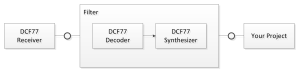
But if you definitely need one you may build it on your own. The Super Filter experiment devliers exactly the necessary code to implement this.

With regard to the library I am planning to push its noise resilence at least two notches further. One notch for even better SNR and another one to deal with signal fading. Ian Castleton provided me with some logs that show how poor the signal is in London. The insights are very interesting. It took about 30 minutes to sync for the first time at 23:30:43 CEST. Then it takes till 23:45:55 to alter between synced and locked. So in total it takes almost 45 minutes to settle to synced. Obviously there is a lot of noise in the signal. Then it stays synced till 14-08-12 2 06:50:00 when it unlocks. It then toggles between lockend and unlocked and arives at 06:50:10 in the state “free”. At 07:19:37 it resyncs. See the details of the log at the end of the article. The point here is that although the signal is very noisy the library easily decodes it. Howevr there is a period of almost an hour where it picks up no reasonable signal at all. Obviously no issue for the clock as it can continue to run on the local crystal. However it is an issue for the frequency auto tune since it requires very lengthy periods where the clock is synced.

This gives me something to ponder about. I am already scratching my head on how to fix this issue. Actually it should be not hard to implement. The real issue is testing this stuff as by now some of the involved time constants are longer than a day.

The log also shows some interesting thing that I did not really think about. As soon as the clock unlocks the convolution bins are of marginal quality at best. It follows that a transition to free is almost unavoidable. Originally I hoped that it might be able to stay in unlocked mode for quite a while. So the original goal at fast recovery of at least the locked state is almost never reached. On the other hand the code is fully tested and performs quite well. One more thing I have to think about. Maybe I should change the conditions for the unlocked -> free and the unlocked -> locked transitions.

Quality (p,s,m,h,wd,d,m,y,st,tz,ls,pm): 0 (2-0:0)(6-0:2)(0-0:0)(0-0:0)(0-0:0)(0-0:0)(0-0:0)(0-0:0)0,0,0,255
Clock state: useless
Tick: 347

Quality (p,s,m,h,wd,d,m,y,st,tz,ls,pm): 0 (5802-4:255)(69-13:9)(105-83:3)(96-76:3)(34-26:1)(68-62:0)(56-49:1)(50-43:1)26,5,13,255
Clock state: useless
Tick: 28462

Decoded time: 14-08-11 1 23:30:43 CEST ..
Quality (p,s,m,h,wd,d,m,y,st,tz,ls,pm): 2 (5804-12:255)(69-13:9)(105-83:3)(96-76:3)(34-26:1)(73-66:1)(56-49:1)(50-43:1)26,5,13,255
Clock state: synced
Tick: 13

Decoded time: 14-08-11 1 23:31:42 CEST ..
Quality (p,s,m,h,wd,d,m,y,st,tz,ls,pm): 2 (5889-12:255)(61-18:8)(112-88:3)(103-81:3)(37-28:1)(73-66:1)(60-52:1)(53-46:1)28,4,14,255
Clock state: synced
Tick: 13

Decoded time: 14-08-11 1 23:31:43 CEST ..
Quality (p,s,m,h,wd,d,m,y,st,tz,ls,pm): 0 (5893-30:255)(61-18:8)(112-88:3)(103-81:3)(37-28:1)(77-71:0)(60-52:1)(53-46:1)28,4,14,255
Clock state: locked
Tick: 13

Decoded time: 14-08-11 1 23:31:44 CEST ..
Quality (p,s,m,h,wd,d,m,y,st,tz,ls,pm): 0 (5873-12:255)(61-18:8)(112-88:3)(103-81:3)(37-28:1)(77-71:0)(60-52:1)(53-46:1)28,4,14,255
Clock state: locked
Tick: 13

Decoded time: 14-08-11 1 23:34:42 CEST ..
Quality (p,s,m,h,wd,d,m,y,st,tz,ls,pm): 0 (5914-6:255)(131-69:8)(133-105:3)(123-95:4)(46-34:2)(85-79:0)(74-63:1)(60-55:1)30,3,15,25
Clock state: locked
Tick: 13

Decoded time: 14-08-11 1 23:34:43 CEST ..
Quality (p,s,m,h,wd,d,m,y,st,tz,ls,pm): 2 (5918-22:255)(131-69:8)(133-105:3)(123-95:4)(46-34:2)(91-84:1)(74-63:1)(60-55:1)30,3,15,25
Clock state: synced
Tick: 13

Decoded time: 14-08-11 1 23:36:54 CEST ..
Quality (p,s,m,h,wd,d,m,y,st,tz,ls,pm): 2 (5839-0:255)(184-115:9)(147-115:4)(136-106:4)(54-41:2)(103-94:1)(89-75:2)(66-61:1)32,1,17,22
Clock state: synced
Tick: 13

Decoded time: 14-08-11 1 23:36:55 CEST ..
Quality (p,s,m,h,wd,d,m,y,st,tz,ls,pm): 0 (5841-14:255)(184-115:9)(147-115:4)(136-106:4)(54-41:2)(103-94:1)(89-75:2)(68-62:0)32,1,17,22
Clock state: locked
Tick: 13

Decoded time: 14-08-11 1 23:45:54 CEST ..
Quality (p,s,m,h,wd,d,m,y,st,tz,ls,pm): 0 (5748-0:255)(171-22:20)(207-161:6)(194-152:5)(77-57:3)(149-135:1)(120-101:3)(90-88:0)44,4,26,20
Clock state: locked
Tick: 13

Decoded time: 14-08-11 1 23:45:55 CEST ..
Quality (p,s,m,h,wd,d,m,y,st,tz,ls,pm): 2 (5770-6:255)(171-22:20)(207-161:6)(194-152:5)(77-57:3)(149-135:1)(120-101:3)(94-88:1)44,4,26,20
Clock state: synced
Tick: 14

Decoded time: 14-08-12 2 06:49:59 CEST ..
Quality (p,s,m,h,wd,d,m,y,st,tz,ls,pm): 2 (16-0:2)(180-25:21)(248-12:33)(249-19:32)(252-2:35)(252-13:33)(252-6:34)(252-11:33)64,50,50,8
Clock state: synced
Tick: 14

Decoded time: 14-08-12 2 06:50:00 CEST ..
Quality (p,s,m,h,wd,d,m,y,st,tz,ls,pm): 0 (14-0:1)(0-0:0)(0-0:0)(0-0:0)(0-0:0)(0-0:0)(0-0:0)(0-0:0)64,50,50,8
Clock state: unlocked
Tick: 13

Decoded time: 14-08-12 2 06:50:04 CEST ..
Quality (p,s,m,h,wd,d,m,y,st,tz,ls,pm): 0 (23-0:2)(6-6:0)(0-0:0)(0-0:0)(0-0:0)(0-0:0)(0-0:0)(0-0:0)64,50,50,10
Clock state: unlocked
Tick: 10

Decoded time: 14-08-12 2 06:50:05 CEST ..
Quality (p,s,m,h,wd,d,m,y,st,tz,ls,pm): 0 (51-0:6)(6-6:0)(0-0:0)(0-0:0)(0-0:0)(0-0:0)(0-0:0)(0-0:0)64,50,50,10
Clock state: locked
Tick: 11

Decoded time: 14-08-12 2 06:50:06 CEST ..
Quality (p,s,m,h,wd,d,m,y,st,tz,ls,pm): 0 (23-0:2)(6-6:0)(0-0:0)(0-0:0)(0-0:0)(0-0:0)(0-0:0)(0-0:0)64,50,50,10
Clock state: locked
Tick: 12

Decoded time: 14-08-12 2 06:50:07 CEST ..
Quality (p,s,m,h,wd,d,m,y,st,tz,ls,pm): 0 (4-0:1)(0-0:0)(0-0:0)(0-0:0)(0-0:0)(0-0:0)(0-0:0)(0-0:0)64,50,50,10
Clock state: unlocked
Tick: 10

Decoded time: 14-08-12 2 06:50:08 CEST ..
Quality (p,s,m,h,wd,d,m,y,st,tz,ls,pm): 0 (21-0:2)(0-0:0)(0-0:0)(0-0:0)(0-0:0)(0-0:0)(0-0:0)(0-0:0)64,50,50,10
Clock state: locked
Tick: 12

Decoded time: 14-08-12 2 06:50:09 CEST ..
Quality (p,s,m,h,wd,d,m,y,st,tz,ls,pm): 0 (0-0:0)(0-0:0)(0-0:0)(0-0:0)(0-0:0)(0-0:0)(0-0:0)(0-0:0)64,50,50,10
Clock state: unlocked
Tick: 10

Decoded time: 14-08-12 2 06:50:10 CEST ..
Quality (p,s,m,h,wd,d,m,y,st,tz,ls,pm): 0 (0-0:0)(6-0:2)(0-0:0)(0-0:0)(0-0:0)(0-0:0)(0-0:0)(0-0:0)64,50,50,10
Clock state: free
Tick: 10

Decoded time: 14-08-12 2 07:19:37 CEST ..
Quality (p,s,m,h,wd,d,m,y,st,tz,ls,pm): 1 (4086-0:255)(157-0:22)(108-84:3)(79-67:1)(38-25:2)(77-66:1)(64-51:2)(50-43:1)90,64,64,39
Clock state: free
Tick: 11

Decoded time: 14-08-12 2 07:19:37 CEST ..
Quality (p,s,m,h,wd,d,m,y,st,tz,ls,pm): 2 (4079-0:254)(157-0:22)(108-84:3)(86-72:2)(38-25:2)(77-66:1)(64-51:2)(50-43:1)90,64,64,39
Clock state: synced
Tick: 13

Decoded time: 14-08-12 2 09:07:31 CEST ..
Quality (p,s,m,h,wd,d,m,y,st,tz,ls,pm): 14 (4612-0:255)(183-0:25)(252-58:27)(254-40:30)(254-135:16)(253-154:13)(255-134:17)(252-156:13)16,8,8,43
Clock state: synced
Tick: 14
[\code]

Posted in Uncategorized | Leave a comment

Soccer Championship vs. my Blog

This month I expected that my blog will see very low page hits. Actually every summer in the last two years page hits were low. And this summer there were also world soccer championships. Something that I expected to drive down numbers even lower.

Do not worry – Germany won the Championships – so I am not going to complain 🙂

However for some reasons that I do not understand the contrary happened. I got significantly increased hit rates – which of course I like a lot. Seems more people are getting interested in my stuff.

Most notably I got very increased hit rates from Italy. Also the Power Grid Monitor was drawing a lot of attention. More than the all time favourite experiment LED Camera. If anyone could explain the sudden rise of attention from Italy and the increased interest in the Power Grid Monitor I would be very pleased to learn about this.

Also I got a lot of feedback for my DCF project. Ian Castleton from Great Britain found some issue with my 1 kHz generator for the DCF77 library. I was setting up timer 2 with some undefined mode which worked anyway by pure chance. Now I am using only officialy documented timer modes. Of course the github repository is already up to date. What I learned from Ian is that DCF77 is pretty popular in GB but they have to deal with really poor signal quality due to the large distance to DCF77. Just like Brett Oliver he also found that my library deals with this issue very well. He even sent me some logs of the signals he received. He gets a really crappy signal but still not even close to the limits for my library. Ian also solved my long standing question at Stackoverflow. He hinted me to the document Performance Analysis and
Receiver Architectures of DCF77 Radio-Controlled Clocks
by Peter Engeler. Without knowing that I was searching for such an article for a long time he provided me with exactly what I wanted. A big thank you to Ian for this.

The highlight for this month was that a colleague got hold of a 3D printer. Of course I immediately designed some enclosures for my Blinkenlighty. I am very pleased with the results.

Posted in Uncategorized | Leave a comment

Automatic Tuning

As promised last month my library now got some more update that exceeds the functionality of The Clock significantly.

It now supports “autotune”. That is the crystal frequency compensation will not require manual optimization anymore. The improved library will auto tune the adjustment. Even better it will retune automatically as long as the library keeps in sync with DCF77.

Frequency_Control

I went even one step further. It even supports persistency for the tuned adjustments. Once the frequnecy is tuned the adjustment will persisted to EEPROM and reloaded from there at the next power cycle.

If you wonder if I applied wear leveling – the answer is no. I computed that on average the library will persist less than once per day. So it would wear out EEPORM after 100 000 days or more than 300 years of continous operation. In my opinion this is something not worry about 🙂

Posted in Uncategorized | Leave a comment

Working with Brett Oliver

Last month I implmeneted the first extension to my library to help Brett Oliver with his new clock.

I struggled quite a bit with the decision if crystal frequency compensation will go into my library or not. After all the goal of this library is maximum noise resilence. Finally I came to the conclusion that a signal outage is some kind of noise. Thus handling it as good as possible is congruent to my goals for this library. Consequently I implemented this.

The next step is to add some autotune feature for the frequency adjustment. Although this is not to hard to implement it takes long to test it. This is not because it is hard – it is because the involved time constants are in the range of days. Thus I just can not test the autotune feature overnight.

Stay tuned for the next release of the library as it will support autotune to 1 Hz or 1/16 ppm.

Posted in Uncategorized | 5 Comments

DCF77 Library planned for some Really Cool Clock

Last month Brett Oliver contacted me. He already constructed some really cool DCF77 synced clocks. Since Brett is located in Great Britain he faces some challenges though.

The biggest challenge is that his current setup gets slightly out of sync every once in a while. This is of course due to noise / issues with the DCF77 sync. Since my dcf77 library is specifically designed to address this issue he is planning to deploy my library. Current test results are very promising. According to him his PC monitor creates loads of noise but my library still keeps perfect sync. As it seems it meets its design goals 🙂

The second challenge is that he is in a different timezone. When I developed the library it did not occur to me that anyone would want to use it outside the CET zone. But since its decoding capabilities are so good I think this is very reasonable. However at this time I do not want to put timezone handling into the library. So I added a timezone conversion example to the simple clock.

Finally he is also concerned about maintenance outages of DCF77. Although I am not very concerned about them I think he has valid point. The issue is that Arduino (even with a crystal) makes a lousy timekeeper. The typical drift of an Arduino (with crystal) is in the order of magnitude of 30 ppm or more than 1 second per day.

There are several ways to fix this. The most obvious one is to add an RTC. Something that I already planned before. However after digging into ntpd I ponder about a software solution. The idea will be to use the DCF77 signal to infer the drift of the crystal and then compensate for it. This should bring the drift down to 1-2 ppm or less than 0.2 seconds per day. This in turn would get rid of a dedicated RTC and make the whole circuit much simpler.

Posted in Uncategorized | Leave a comment