
This library collects the hard part of The Clock into a reusable library. With this library you can have the same extraordinary noise tolerance for your own clock projects. In case you wonder what exactly “extraordinary noise tolerance” means read on here.
Before we go into the details have a look at the architecture overview picture. It is somewhat similar to the architecture of “The Clock”.
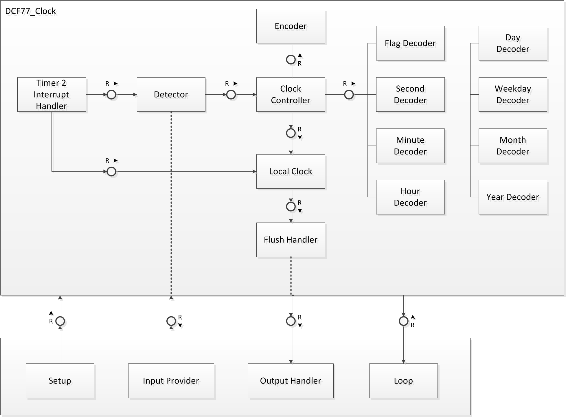
The differences are mainly due to the fact that I only wanted the decoder stuff in the library. Unlike other DCF77 libraries this library is not bound to any specific means of signal acquisition. Especially it is not bound to any pin at all. Instead it executes the inputprovider callback each millisecond. The input provider must be of type typedef uint8_t (*input_provider_t)(void);. That is it must have no arguments and return either 0 or 1 depending on the current state of the DCF77 signal.
Once per second it will execute the output handler callback and pass the current time to it. The output handler if of type typedef void (*output_handler_t)(const time_t &decoded_time);
These callbacks can be set with the functions
DCF77_Clock::set_input_provider
and
DCF77_Clock::set_output_handler.
The input provider is mandatory the output handler is optional. If you do not set the output handler the clock will work anyway. However the output handler is very convenient in order to set a display in sync no matter what the main loop of your sketch is currently processing.
Alternatively you can retrieve the current time by calling the functions
DCF77_Clock::void get_current_time(time_t &now); // blocking till start of next second
and
DCF77_Clock::void read_current_time(time_t &now); // non-blocking, reads current second.
This sounds slightly complicated but it is very simple in practice. In order to illustrate the concept I included some examples with the library. You can download everything from github.
Examples
The library includes some examples to get you started.
DCF77 Scope
The DCF77 Scope does not rely on the library at all. It is an analysis and troubleshooting tool. If this tool does not give reasonable results the library will not work.
Swiss Army Debug Helper
The Swiss Army Debug Helber is the advanced version of the DCF77 Scope. It relies on the library and gives you lots of internal information. If the DCF77 Scope works correctly but the debug helper does not then you most probably have compiler issue. See the Software Incompatibilities below.
Simple Clock
The Simple Clock implements a rudimentary DCF77 clock to exhibit the basic functionality of the library.
The Clock – Library Version
The Clock – Library Version is the library based version of The Clock. This is the code that started it all.
Meinberg Emulator
The Meinberg Emulator emulates a Meinberg DCF77 Clock. I implemented it because it was easy and because there are some NTPD Meinberg Drivers out there.
Super Filter
The Super Filter is intended as a drop in enhancement for existing DCF77 projects. Just put the Super Filter between the DCF77 module and your existing gadget and you will have all the benefits of my library without touching your code. It basically decodes the signal and re-synthesize it. Thus you will get a 100% clean signal.
Download
You can download the library and the examples from github.
Gallery
Brett Oliver uses my Library for his incredible DCF77 master clock as well as for his Binary Clock.
Eric de Euiter uses my Library and the Super Filter for his DCF77 clocks. See the results of his first tests here.
Performance
The key to the outstandind noise tolerance of this library is the phase detection algorithm. Of course I added a stack of complex algorithms on top of it. If you understand this algorithm (or at least the implications of my analysis) you know why my library is so much better than a naive straightforward implementation.
Hardware Incompatibilities
My library will not work with a “modern” Arduino Uno. The Uno utilizes a resonator instead of a crystal. Since a resonator has a less stable clock this in turn would decrease the noise tolerance significantly. It also would require different constants for the phase lock. Since my goal is to push the noise tolerance to the limits I will offer no support for this platform. You have several options:
- get hold of an “old style” Arduino like e.g. the Blinkenlighty (which would also help to fund my blog).
- replace the Uno’s resonator with a crystal or a crystal oscialltor (requires some soldering skills)
- dig into my library and modify the time constants (possible, but gives poorer results, I neither recommend nor support this approach)
Software Incompatibilities
The initilization code for this library will stop timer 0 interrupts. Thus the Arduino’s millis() function will not work properly anymore. This is usually not an issue since my library is already keeping time, thus there should be no need for a redundant time keeping mechanism. If you absolutely require the Arduino’s standard time keeping you may activate it by setting TIMSK0 accordingly. However you need to understand that I never tested this setup, thus it might decrease the library decoder performance. Only reactivate this if you understand the implications of race conditions.
The library also reprograms timer2. Thus anything that relies on control of timer2 (e.g. msTimer2) will interfere with my library.
The library works fine with my Arduino 1.0 installations on Ubuntu. However for standard versions of Arduino (1.0 – 1.0.6) it compiles but fails to acquire a signal lock. The nasty reason for this is that the Arduino guys bundled an outdated version of avr-gcc with the newer versions of Arduino.
The simplest solution is to upgrade to Arduino 1.5.8 Beta or above. This is because with 1.5.7 Beta Arduino is bundled with a brand new version of AVR-GCC.
Pin Mappings
Some readers wondered to which pins my library maps. The answer is: none. This library was designed to be completely pin agnostic. This of course rises the question how this library learns about the signal. The answer is that YOU have to provide the code for sampling the desired input pin. An example of how to do this is in the simple clock implementation. Watch out for the function “sample_input_pin()”.
Some readers also wondered what the meanings of the constants in my examples are. Of course I described them somehwere in my blog. But if you do not want to go through all of my articles here is the list of some standard constants that I use.
If these constants do not suit your needs, just change them. The library has no implicit dependency to any pin at all. So you can use any pin as long as it is not in use for something different.
| name | typical value | comment |
|---|---|---|
| dcf77_analog_sample_pin | 5 | input pin for analog sampling |
| dcf77_sample_pin | 19 | input pin for digital sampling, notice D19 == A5 |
| dcf77_inverted_samples | 1 | 0 or 1 depending on your DCF77 module |
| dcf77_analog_samples | 1 | 1 => analog sampling, 0 => digital sampling, Blinkenlighty needs analog samples see comment below |
| dcf77_monitor_pin | 18 | displays the signal the software received, common Arduinos might want to use 13 because this is connected to the only LED |
With regard to the analog vs. digital sampling. Analog mode will work with any Arduino I know. However it consumes slightly more resources. For the Blinkenlighty it is the only admissible mode if you do not want to disconnect the LED bar. So set this to 1 for the Blinkenlighty. For all others you may want to set this to 0.
Depending on this mode either the sample pin or the analog sample pin will be evaluated. Of course these constants may point to the SAME pin. In digital mode the digial sampling pin is used in analog mode the analog sampling pin is used. The choice of the mode has absolutely no effect on the noise tolerance. In the end it only controls the threshhold between a “low” and a “high” signal.
If you are unsure about the pin mappings use the DCF77 scope with your pin mappings to verify if you got them right.


I’m currently looking into adopting the library in one way or another. More specifically I want to improve the decoding robustness for a Wordclock project [1]. However, I’m not sure as to whether your library is suitable for our situation, because we use the internal RC oscillator of an Atmel ATmega168/328.
If it shouldn’t be possible to adopt your library directly, it would be great to get some advice for implementing a solid and robust filter on our own. Knowing what you know now (after having spent a couple of months dealing with all of this), what would you personally suggest is a good compromise between spent effort (time, code size) and actual improvements. Personally I’m of the opinion that the exponential filter approach looks the most promising, because it is relatively straight forward to implement and according to your blog entry improves the decoding capability by a lot.
I have another couple of questions, which are more subjective and I’m asking them just out of interest:
– Have you ever dealt with DCF77 modules that would only return a low level in cases they are interfering with some PWM signal? I’ve two modules that are permanently low in some instances, so filtering in software won’t even work. What can be done about this?
– Do you know about the capacitor mod for Conrad DCF77 modules proposed in the current “c’t Hardware Hacks”? They suggest to add a decoupling capacitor parallel to a diode on the module, which seems to improve the quality of the signal. Personally I haven’t observed any improvement, so I’m not sure as to whether this makes any difference at all.
– Have you noticed any difference in the modules from Pollin, Conrad and Reichelt? Only recently I’ve made the experience that the ones from Pollin seem to be more robust. Given that they only cast half as much as both of the other options, I’m really confused. Unfortunately they don’t work with TTL (5 V) logic, so you need some external components for the level shifting. What are your thoughts on this? I’m not talking about the industrial receiver(s) you have worked with here ;).
[1]: https://www.mikrocontroller.net/topic/156661
The *best* solution regarding time and spent effort is to use an out of the box solution. For example HKW sells modules with internal clock. Taking opportunity cost into account this is the most efficient solution.
Now if you want to follow the diy path the next best thing is to get a reasonable receiver module and a big antenna. I compared several DCF77 receiver modules. Again the professional solution wins. Especially because it will work with a bigger antenna (bigger is better here).
The HKW module (like most of the professional modules) has a wider bandwidth. The cheap modules have a narrower bandwidth. The reasons why are intricate but this has the implication that the professional modul will pick up more (sic!) interference. I suspect that this is the reason why the professional modules seem to have better automatic gain control. The AGC seems to be the reason why the cheaper modules will flatten out if there is to much noise.
Now with regard to the optimal filter approach. I would suggest to add a crystal oscillator. They come out of the box as complete modules and will cost you only one pin. Then you can use my super noise resistant library. In the last test I laid an active Smartphone on the Antenna. The HKW module’s signal went mad but the module continued to demodulate the crap. The library decoded the signal within ~30 minutes although there was no minute with at least 10 bit errors.
If you do not want to go for a crystal and not for a smarter DCF module then I see only two more options:
1) Use the exponential filter approach . But remember that the libary can deal with 15 dB worse SNR.
2) Use a diy smart module. That is use another 328 with my library in it and use it to locally synthesize DCF77 again. I am very sure that this would even beat the HKW smart decoder module. If you are interested in this approach I would publish a sketch for it.
With regard to filtering of powerline noise forget about the magic capacitor approach. The only reliable solution is to nail down the root cause. Get an oscilloscope or find one who owns an oscilloscope and determine what is going on. Once this is understood fix the root cause (e.g. add suitable caps or inductors or replace the power supply or whatever else might fix it). Then measure again and verify that you solved it. Anything else is just searching in the dark == a big waste of time.
Unfortunately, adding an oscillator to the existing circuit is not really an option. Building a secondary board and connecting it via SPI / I2C on the other hand might be worthwhile. On the other hand the most annoying problem for me is that the modules won’t return anything when they are in a high noise environment, so a secondary circuit will not necessarily help with that. However, I’m not sure what exactly is going on, because looking at the powerline with an oscilloscope does not look suspicious. Maybe some EMF issues, but I neither have the capability to examine this, nor do I know how to fix it.
Have you planned (or are you interested in) building a module (based on AVRs) hosting your code? I think this might be a good idea after all, so other projects could simply ask for the decoded time (and some status information) via SPI / I2C and/or any other arbitrary protocol (1-Wire).
Yes I put some thought into it but due to EEW regulations in Europe this would be prohibitive expensive, so I ditched this idea.
Do these regulations really apply if you sell a PCB for other hobbyists? Maybe you could sell it as a kit? It seems to work fine for other projects …
Unfortunately they apply. I have registered for business (because that way I can order stuff that I would not get otherwise). However this also implies that authorities can assume that I know what I am doing. I already analyzed the issue and EEW definitely applies to me. This was the reason why the Blinkenlight Kit was first sold in the US. It was also the reason why I teamed with Franzis to sell the shield in Germany. I would have to check if Franzis or some other distributor would be willing to pick up my DCF stuff. IMHO the easiest way would be to take some prefabricated Atmel board that features a crystal. These are available for 15 Euro or less. Then just flash my code to it and connect whatever DCF77 module you want. I suggest HKW modules which are around 20 Euro. Pollin modules are also OK for their price but I will always go for quality. Now suppose I would sell this as a kit. Then we would end up around 50-60 Euro because I also have to account for the associated risk. Would there be any demand at this price point? I doubt this. Reason: IMHO the only demand is from people at some expert level. These people could easily source the stuff wherever they want and just flash my library to it.
I’m trying to get your DCF-77 Library working with a “Freaduino MEGA2560 White Color” Board, which features a crystal and has a reasonable clock deveation of about 200ms every 3600 seconds resulting in a shift of 888 Hz. I use an EM2S-DCF Module and the AFET100-77,5-DD antenna from HKW-Elektronik.
I’m on a Mac and tried with the available Arduino IDEs. With Arduino 1.0.0 and Arduino 1.0.5 (with avr-gcc version 4.3.2) i can compile and run the DCF77_Scope example which shows the beforementioned clock deveation.
The “Simple_Clock” and “The_Clock” sketches also compile and run on the board, but i never get the time output.
When i use Arduino 1.5.7 beta with “Simple_Clock” i get the following error when compiling:
/Users/karl/Documents/Arduino/libraries/dcf77_library/dcf77.cpp: In function ‘void DCF77_Encoder::_ZN13DCF77_Encoder14advance_minuteERN5DCF7711time_data_tE.part.4(DCF77::time_data_t&)’:
/Users/karl/Documents/Arduino/libraries/dcf77_library/dcf77.cpp:3142:1: internal compiler error: Bus error: 10
}
^
libbacktrace could not find executable to open
Please submit a full bug report,
with preprocessed source if appropriate.
See for instructions.
The revisions.txt of Arduino 1.5.7 beta says “Upgraded AVR toolchain: gcc 4.8.1, avr-libc 1.8.0”.
I read your post on the arduino-forum regarding the avr-gcc issues on linux, but couln’t figure out if i have the same problem:
http://forum.arduino.cc/index.php?topic=218014.0
Any ideas how i can get this working?
(The Hardware works flawlessly with the DFC-77 library of Thijs Elenbaas, but not in the specific place where i need it to be working, because of bad signal quality)
4.3.2 is definitely outdated. I never tried 4.8.1. I use 4.5.3. I suggest you give 4.5.3 a try and see how if it compiles.
I’m doing some tests using Arduino 1.5.7 Beta, beacuse avr-gcc 4.7.0 crash compiling everything for mega2560 and I can’t find 4.5.3 for windows. I get this error:
Arduino:1.5.7 (Windows XP), Scheda:”Arduino Mega or Mega 2560, ATmega2560 (Mega 2560)”
\Arduino\libraries\dcf77_library\dcf77.cpp: In function ‘void DCF77_Frequency_Control::process_1_Hz_tick(const DCF77::time_data_t&)’:
\Arduino\libraries\dcf77_library\dcf77.cpp:2971:70: error: using temporary as lvalue [-fpermissive]
((DCF77::time_data_t)decoded_time).leap_second_scheduled = true;
^
\Arduino\libraries\dcf77_library\dcf77.cpp:2979:70: error: using temporary as lvalue [-fpermissive]
((DCF77::time_data_t)decoded_time).leap_second_scheduled = leap_second_scheduled;
^
Searching arount internet I’ve found some indication to add -fpermissive to compiler flags. Adding this flag the compiler crash and tell to report the crash as gcc bug.
I have no idea why avr-gcc 4.7.0 crashes. But it is definitely a compiler issue. Arduino ships by default with an outdated compiler. I am currently using avr-gcc 4.5.3 Would you mind to try 4.5.3? If you tell me the settings for the “inverted mode” I could compile a “debug helper” for you board. Did you need to modify anything for the timer setup or did it work? I am asking because I have no Atmega 2560 around. So if some modifications are needed for the timing I would need this piece of code.
If there is no 4.5.3 for windows I can only recommend to boot Linux from an USB stick. Although Linux might be unfamiliar to you the Arudino IDE looks exactly the same.
I can not try on the real card at the moment (failure of power supply and failure of all attached devices ….. But replacements are coming.), So I’m just compiling the code. I’ve never tested the library on Mega2560 Because I was never able to complete the scketch.I think that could be nice modify the library to use automatically timer4 or 5 or 6 if the target is Mega2560 (so standard arduino funtions aren’t compromised). I’m also looking for a way to compile using beta arduino ide. The error “using temporary as lvalue” is not really a compiler issue but a new working mode of gcc that need some code changes.
I agree that it would be nice. However I do not have a 2560 board, so I can not test this. I suggest that you check out my code from github here. Then add the necessary stuff. Once you tested it issue a pull request and I will integrate it into the code base. The only stuff that you need to change is the implementation of
void init_timer_2(). In addition theISR(TIMER2_COMPA_vect)has to be replaced by a vector that is suitable for your timer. Both reside close to the end of dcf77.cpp. You do not need to deal with macros to find out which board you are on, I would add this part of the code.I followed Andy Browns instructions and installed avr-gcc 4.7.0 with Arduino 1.0.0 on Windows, which you were refering to as well. With the Scope sketch the serial monitor shows the following:
1, +———+———+———+———+———+———+———+———+———+———
2, 52——–+———42——–+———42——–+———42——–+———42——–+———
3, 42——–+———42——–+———42——–+———42——–+———42——–+———
4, 42——–+———42——–+———42——–+———42——–+———42——–+———
5, 42——–+———42——–+———42——–+———42——–+———42——–+———
6, 42——–+———42——–+———42——–+———42——–+———42——–+———
[…]
And the Simple_Clock sketch still does not sync.
As i also didn’t find any information about how to install avr-gcc 4.5.3 (or a similar version) with the Mac Arduino IDE (and my attempt with Ubuntu 14.04. also installed the latest version of avr-gcc) i’m about to give up and order a HKW-Elektronik FUM1 FSK module, which would do the decoding for me.
Though it would be great if you could provide information about how to get a setup for compiling your DCF77 library on Mac, Windows and Linux. Greetings and thanks!
Of The scope shows that you are NOT picking up any DCF77 signal. There are several possible reasons.
Hence I would be more than surprised if it would pick up anything at all.
Finally i get the sync! Thanks!
Although it’s strange. I had the same circuit connected to the same computer and uploaded the same sketch. At first with the Mac Arduino IDE and then with the Windows Arduino IDE (inside a Parallels Desktop VM), and it didn’t work. Now i tried again copy/pasting the sketch from one IDE to the other and it worked. Finally!
If i find the time i will try to get avr-gcc 4.5.3 running with the Mac Arduino IDE. In case i succeed i’ll make a post.
Excellent. May I ask in which environment the clock will be running? That is: what is will be causing your noise issues?
It’s going to be in a building in Vienna, which i haven’t seen myself yet. Until now i just sent a test setup with the Conrad Elektronik DCF module and the 100mm HKW antenna and an Arduino sketch building upon the library of Thijs Elenbaas. They could get a signal in one floor of the building which has windows, but not in the floor where the clock will be installed. The walls in that floor seem to be made out of reinforced concrete. My plan is to deliver another test setup with your library and the HKW module now.
Hello,
I started to test your DCF77 lib with the noise reduction algorithm.
Works fine!. But it uses the Pin A5 and I want to use this pin for I2C.
All tries to connect to another pin failed…. Does it work with a different pin and how?
Thanks, Danke. Andreas
The library has no intrinsic pin binding. All binding happens by the calling program. It can be bound to any pin as long as this pin is not in use otherwise. Just change the constants accordingly. I will make the section “pin mappings” a little bit more explicit on this topic.
Hi, I’m playing round your library to develope a clock. I need to play tones on a piezio speaker, but all library use millis(), and this funtion was compromised by your library. I’m not a good programmer bue I see that the library has an internal function called 1000 times as second, so is simple to add a method that do the same thing as original millis(). Are there a way to override millis() in a transparent way so all libraries that use this function still work?
Hi, as far as I know there is no such way. To achieve this it would be necessary to somehow write to the variable
volatile unsigned long timer0_millis = 0ofwiring.cAlternatively it would be necessary to replaceunsigned long millis()fromwiring.c.I am not aware of any way to achieve this “transparently” without actually patching
wiring.c. If you would give more details on what you are actually trying to achieve (more details means CODE) then maybe I can find a better solution.I haven’t the code here but the example is simple to explain.
I have to use this library: http://playground.arduino.cc/Code/ToneAC
This library generate a tone (note), forever or for a specific time. To track the note duration it use millis(). I could use the funcitons toneAC()/noToneAC() to start/stop the notes and generate the melody, but I need some calls that give me a time with at least 5ms of resolution, better if 1ms. So a function, on your library, that return a values as millis() do or that return current time with 1/1000s resoultion can be a good workaround.
Have a look at the https://blog.blinkenlight.net/experiments/dcf77/simple-clock/ example. The sample_input_pin method is called once per millisecond. Thus if you could define a global counter
volatile unsigned long my_millis;Then increment this counter in sample_input_pin, e.g. put
++my_millis;as the first line intosample_input_pinThen use something like
unsigned long read_my_millis() {

    const uint8_t oldSREG = SREG;

    cli();

    const unsigned long m = my_millis;

    SREG = oldSREG;

    return m;

}
To read the desired milliseconds. Do not use my_millis, otherwise you will get some nasty race condition.
Fantastic!!!!!! 🙂
Do you have any thoughts on where/what changes would be required to adapt your filtering methods and library to other time code formats such as used by MSF, JJY, or WWVB? For example, DCF uses .1S and .2S carrier reductions for 0s and 1s except the last second while WWVB uses .2S and .5S for 0 and 1, but also has a .8S marker every 10S. There are also MSB/LSB first differences but I think I can handle that. Any pointers would be appreciated!
Sorry for the late answer but I was two weeks on vacation without ANY internet access. Seems you have been reading my mind. This is exactly what I was asking for with my https://blog.blinkenlight.net/2014/11/01/wouldnt-it-be-nice/ article 🙂
I suggest to proceed as follows:
0) Ensure you have version control in place. This is going to be a somewhat longer project. I recommend GIT https://blog.blinkenlight.net/2013/11/01/all-you-can-git/ but if you are familiar with a different version control systems it will be just as good.
1) Ensure that you have suitable hardware. “See hardware incompatibilities” for the details. I suggest two Arduinos with crystal oscillators for reasons that will become apparent soon.
2) Ensure that my library compiles properly. That is ensure that your installation has a suitable compiler. See the “software incompatibilites”. The simplest way is to ask gcc for its version. The recommended way is to run the “swiss army debug helper” https://blog.blinkenlight.net/experiments/dcf77/swiss-army-debug-helper/ vs any module DCF77, WWVB or MSB/LSB and see if it drifts. If not everything is fine.
3) As a first implementation step I suggest to implement a [WWVB|MSB|LSB]_ENCODER. Instead of the DCF77_ENCODER. This namespace can then be used to implement an emulator to create arbitrary time signals (similar to the way I implemented for the superfilter: https://blog.blinkenlight.net/experiments/dcf77/super-filter/). This step is needed sooner or later as the encoder is used in the decoder logic as well. I would implement it as early as possible since this is one of the easiest parts and it established test capabilities. Now it should be obvious why I recommended two Arduinos in step 1.
4) Then I suggest to proceed with an implementation of the phase lock logic. Instead of modifying the library I would first reimplement the standalone version https://blog.blinkenlight.net/experiments/dcf77/phase-detection/. What you need to do is to figure out a proper filter kernel and tweek the summation logic accordingly. This is by far one of the trickiest parts. Therefore it should be implemented and tested in a standalone version. Once this works as desired move it into your library. Do not forget to test if this can deal with a noisy signal. If the phase lock fails the rest of the decoder will fail.
5) The next step is the second decoder. Again I suggest to reimplement the standalone version https://blog.blinkenlight.net/experiments/dcf77/second-decoder/ first. Here you need to figure out where there are suitable markers in your signal and how to deal with them.
6) Once the second decoder is implemented the minute / hour / month / year decodes can be ported. This can be done stepwise. But you have to start with the minute decoders and go on to the hour / month / day / year decoders as they are cascaded. All of them are implemented in a similar fashion so once you are through with the minute decoder the others should be somehwat easy.
7) Then you need to take care of the summer / winter time and leap seconds flags. Use text search to find where this stuff is located and adapt it.
8) Adapt the convolution binning. Until you adapt this you should search for the string “convolution_binning_not_ready” and ensure that the corresponding if condition will always go for “sync_mark_binning”.
9) After each step test your stuff. I am willing to help review the implementations but I may not have enough time to debug your code. If you have any questions just ask.
Thanks for the detailed reply. It will be a bit of work for me (I still have to grock the whole C++/OO thing forgetting my decades of procedural thinking and then more fully understand your code). I’ve forked your github library and will work from that. If I get anything useful completed I’ll contribute back of course. Thanks for documenting and sharing everything. It’s appreciated.
Hi Paul,
I was also considering adapting the DCF77 library for use with MSF and am wondering if you have made any progress with this over the past couple of months?
https://github.com/udoklein/dcf77_library/issues/3#issuecomment-68680793
Sadly, no. “RealLife” has interrupted things. However… I did just pickup again on another part of this project. I also have some basic WWVB encoder routines but they do not encode all possible bits yet. And by the way, it was just announced that we will be having a leap-second this year, so this will be a chance to check libraries against these rare occurances. I have not yet begun the DCF77 library porting though.
Hi Paul,
Thanks for the speedy response.
OK, I’m going to fork the DCF77 library in github and start working on an MSF library.
I’ve only just started looking at the code but my initial thoughts are to maybe split the DCF77 library up into generic radio time signal code and DCF77 specific code. Then add some MSF specific code also. This will make the library a bit more modular so that other modules (WWVB etc.) may be added later. Hopefully I’ll find out quick enough if this is a good approach or not.
Hi Udo/Paul,
I have done some work on adding MSF functionality to the DCF77 Library. It can be found on github at:
https://github.com/aido/RadioClock/tree/MSF
It is currently untested but, as mentioned above, what I’ve done so far is first split the existing code into generic RadioClock functionality and DCF77 specific functionality. I then added MSF specific functionality.
It’s a first draft and still a bit rough and untested. I would still appreciate your comments or suggestions.
Amongst other things, in sync_mark_binning() I am currently not sure how best to use the fact that with an MSF signal bit A positions 52 to 59 are always 01111110. These 6 consecutive 1 bits thus uniquely identify the end of the minute.
If you have any comment on the code maybe create issues on the github page rather than flood the blog here.
Hi Udo,
thanks for pulishing extreme usefull dcf77 lib. With DCF_Simple_Clock example as a starting point and minor modification DCF_Simple_Clock now runs with the cheap Pollin receiver displaying date and time on a 16*2 LCD-display.
However beeing a newbee I wonder how to display weekday. It might be a silly question so pls add a hint where to find information on this issue.
Thanks Jochen
You want to look into the libraries header file. There you can see the declaration of DCF77_Clock::time_t. The weekday field is called “weekday”. If you start with the simple clock then you might just add a line
serial.println(now.weekday).serial.println(now.weekday) works fine however I didn’t managed to use now.weekday as an index of a character array (containing “Mon”, “Thu”,…)
Stupid question I know but beeing a C++ newbee …
Thanks
Jochen
btw: weekday is not highlighted in the listing as all the other now.xxx items
Have a look at http://arduino.cc/en/pmwiki.php?n=Reference/PROGMEM “Arrays of Strings”. However notice that the piece of code
    char buffer[30];    // make sure this is large enough for the largest string it must hold
...
    for (int i = 0; i < 6; i++)
    {
        strcpy_P(buffer, (char*)pgm_read_word(&(string_table[i]))); // Necessary casts and dereferencing, just copy.
        Serial.println(buffer);
        delay( 500 );
     }
wastes memory for the output buffer “buffer”. I recommend to ommit the buffer and instead implement it as follows.
#define FS(s) reinterpret_cast<__FlashStringHelper *>(s)
#define FSA(s) FS(pgm_read_word(& s))
...
    for (int i = 0; i < 6; i++)
    {
        Serial.println(FSA(string_table[i]));
        delay( 500 );
    }
Or go for the Arduino flash library https://github.com/mikalhart/Flash/blob/master/examples/flash_example/flash_example.pde
Hi.
I´m using your lib for the first time and yes, i´m happy that i found it.
I have a little Problem, might be located between my ears 😉
This is my init Code:
pinMode(dcf77_sample_pin, INPUT);
digitalWrite(dcf77_sample_pin, dcf77_pull_up);
DCF77_Clock::setup();
DCF77_Clock::set_input_provider(sample_input_pin);
I´m using it on a DUE and tried different input PINs.
As long as the Clock was not synced or locked i call “DCF77_Clock::get_current_time(now);” once a minute. After the Clock was in sync only once a hour.
My Problem was that after the Clock was in sync or locked i can´t use my Touchpanel anymore. It reacts only from time to time.
Can this caused by the output_handler? If i´m right, this function was called every second – right? I didn’t use this function and didn´t declare it. As long as the Clock was not in sync everything was running smoth.
Thanks in advance for any help or hint.
Best Regards // André
Which version of my library are you using and where can I see the complete code? Unless I see your complete code I have to assume that the issue is indeed between your ears.
Hi.
I am on a bussines Trip for the next two or three Weeks and have nothing with me.
I only can say that i´m using the actual Version 3 of the Lib.
I will come back to you as soon as i´m back @home.
Many thanks and best Regards
André
Hello, i was trying to use this library for some kind of wall clock at home, using the
radio module as time/sync source.
I’m not able to get time with it, even if it seems to receive a signal
well, and i’m not really sure about what can be wrong.
This is the module i am using
http://www.mas-oy.com/uploads/Data%20sheets/DAEV6181B1COB.pdf , since
it is dualband it has two control pins in order to turn off, and use 77
or 60khz bands.
I’m using an atmega328p, with the 3.3v and 8mhz bootloader (it works
fine per-se on other things)
On the example sketches i add:
pinMode(4, OUTPUT);
digitalWrite(4, HIGH);
pinMode(2, OUTPUT);
digitalWrite(2, LOW);
delay(50),
on the setup section (just at the start), that sets the module to use
the 77khz band (or should), i use pin3 (interrupt 1) as the input for
the time signal (i attach some pics of the wiring)
On the DCF77_Scope i get:
*******************************
21, +37XXXXXXXXXXXXXXXXXX73——-+———+37XXXXXXXXXXXXXXXXXX73——-+———+37XXXXXXXXXXXXXXXXX
22, X73——-+———+37XXXXXXXXXXXXXXXXXX73——-+———+37XXXXXXXXXXXXXXXXXX73——-+———
23, +37XXXXXXXXXXXXXXXXXX73——-+———+37XXXXXXXXXXXXXXXXXX73——-+———+37XXXXXXXXXXXXXXXXX
24, X73——-+———+37XXXXXXXXXXXXXXXXXX73——-+———+37XXXXXXXXXXXXXXXXXX73——-+———
25, +37XXXXXXXXXXXXXXXXXX73——-+———+37XXXXXXXXXXXXXXXXXX73——-+———+37XXXXXXXXXXXXXXXXX
26, X73——-+———+37XXXXXXXXXXXXXXXXXX73——-+———+37XXXXXXXXXXXXXXXXXX73——-+———
27, +37XXXXXXXXXXXXXXXXXX73——-+———+37XXXXXXXXXXXXXXXXXX73——-+———+37XXXXXXXXXXXXXXXXX
28, X73——-+———+37XXXXXXXXXXXXXXXXXX73——-+———+37XXXXXXXXXXXXXXXXXX73——-+———
29, +37XXXXXXXXXXXXXXXXXX73——-+———+37XXXXXXXXXXXXXXXXXX73——-+———+37XXXXXXXXXXXXXXXXX
30, X73——-+———+37XXXXXXXXXXXXXXXXXX73——-+———+37XXXXXXXXXXXXXXXXXX73——-+———
*****************************
I use:
const uint8_t dcf77_sample_pin = 3;
const uint8_t dcf77_inverted_samples = 1;
const uint8_t dcf77_analog_samples = 0;
const uint8_t dcf77_pull_up = 0;
Using the sync examples i can leave it running for 30min and it only
shows “Initializing……………” all the time, no date or time
Do you know what could be wrong or where could i look? (i’m not really a programmer so i’m
limited on the code side).
Thanks!
Hi Victor thanks for the detailed description. There are (at least) two issues why this fails.
I suggest to first find a module that actually delivers DCF77 output. Then I suggest to go on with a 16 MHz setup.
Hello, the output must be dcf77, i asked the manufacturer and that’s what they say, also running a simple sketch to measure the pulses i see 100 and 200 ms pulses (not exactly but close to the ranges you’d expect i think) like this:
**************************
60s # 65ms
60s # 119ms
61s # 74ms
61s # 11ms
61s # 120ms
61s # 187ms
61s # 49ms
61s # 9ms
61s # 9ms
61s # 35ms
62s # 40ms
62s # 3ms
…
120s # 16ms
120s # 124ms
120s # 63ms
120s # 31ms
120s # 10ms
120s # 48ms
120s # 1ms
120s # 60ms
120s # 80ms
121s # 48ms
121s # 235ms
121s # 14ms
121s # 13ms
121s # 22ms
***************************
This output looks OK. But the output of my scope code did not look OK. So probably you have some issues with your pin setup.
As Arduino now supports the ESP8266 module (cheap and impressive features) pls have a look at the board dependencies of the library. Maybe/hopfully you can remove them 🙂
Have a look at the compiler messages here:
——————–schnipp————————–
Arduino: 1.6.5 (Windows 8.1), Platine: “Generic ESP8266 Module, Serial, 80 MHz, 40MHz, DIO, 115200, 512K (64K SPIFFS)”
Build-Optionen wurden verändert, alles wird neu gebaut
In file included from Simple_Clock.ino:19:0:
C:\Users\Jochen\Documents\Arduino\libraries\dcf77-development/dcf77.h:621:10: error: #error Unsupported controller architecture
#error Unsupported controller architecture
^
C:\Users\Jochen\Documents\Arduino\libraries\dcf77-development/dcf77.h: In member function ‘void Internal::Binning::bins_t::get_quality(Internal::Binning::bins_t::lock_quality_t&)’:
C:\Users\Jochen\Documents\Arduino\libraries\dcf77-development/dcf77.h:686:17: error: ‘CRITICAL_SECTION’ was not declared in this scope
CRITICAL_SECTION {
^
C:\Users\Jochen\Documents\Arduino\libraries\dcf77-development/dcf77.h:686:34: error: expected ‘;’ before ‘{‘ token
CRITICAL_SECTION {
^
C:\Users\Jochen\Documents\Arduino\libraries\dcf77-development/dcf77.h: In member function ‘uint8_t Internal::Binning::bins_t::get_quality_factor()’:
C:\Users\Jochen\Documents\Arduino\libraries\dcf77-development/dcf77.h:696:17: error: ‘CRITICAL_SECTION’ was not declared in this scope
CRITICAL_SECTION {
^
C:\Users\Jochen\Documents\Arduino\libraries\dcf77-development/dcf77.h:696:34: error: expected ‘;’ before ‘{‘ token
CRITICAL_SECTION {
^
C:\Users\Jochen\Documents\Arduino\libraries\dcf77-development/dcf77.h:796:13: error: expected ‘}’ at end of input
}
^
C:\Users\Jochen\Documents\Arduino\libraries\dcf77-development/dcf77.h: In member function ‘void Internal::DCF77_Local_Clock::read_current_time(Internal::DCF77_Encoder&)’:
C:\Users\Jochen\Documents\Arduino\libraries\dcf77-development/dcf77.h:1720:13: error: ‘CRITICAL_SECTION’ was not declared in this scope
CRITICAL_SECTION {
^
C:\Users\Jochen\Documents\Arduino\libraries\dcf77-development/dcf77.h:1720:30: error: expected ‘;’ before ‘{‘ token
CRITICAL_SECTION {
^
Fehler beim Kompilieren.
Dieser Report hätte mehr Informationen mit
“Ausführliche Ausgabe während der Kompilierung”
aktiviert in Datei > Einstellungen
——————–schnapp————————–
Thank you!
This is open source. See my standard comment here: https://blog.blinkenlight.net/2014/11/. If you want support for this board you have to provide 3 things:
If you are not willing to provide the work why should I? The issue is that I am not that interested in these boards. In particular I have no clue if it is even possible with them. As soon as their is network activity this might interfere with the timers –> testing is much more tricky than with standard boards.
If you provide tested code and others confirm that it works I will integrated it. But do not expect that I work for free on request.
Hello again Udo (it won’t let me answer to your last message so i write this separately), this is the sketch i use for the signal example:
*******************
unsigned long duration;
void setup() {
pinMode(3, INPUT);
//needed to select 77Khz band –>
pinMode(4, OUTPUT);
pinMode(2, OUTPUT)
digitalWrite(4, HIGH);
digitalWrite(2, HIGH);
delay(100),
digitalWrite(4, HIGH);
digitalWrite(2, LOW);
Serial.begin(9600);
}
void loop() {
duration = pulseIn(3, LOW); //datassheet says signal on = low
Serial.print(millis()/1000);
Serial.print(“s # “);
Serial.print(duration/1000);
Serial.println(“ms”);
}
******************
Do you know how would i need to translate it for the library? I mean, i was using the same setup() part on the library scope so the only difference could he how it is listening for the input, no?
Thanks
How do you expect me to find any issues if you just give me partial pieces of the code. Upload your code as a whole to some site (e.g. Arduino Forum or as Github Gist or some dropbox) and tell me which version of the library you use. Otherwise I have not even a tiny chance to figure out what you did. Also I would need you exact setup, which version of Arduino are you running and which controller do you use? How did you wire it, what happened, what should have happened and why do you think my code is to blame?
Looking at the logs the issue appears to be with your wiring / pin assignments.
Hello Udo, by searching the web for a noise tolerant DCF77 decoder algorithm, I stumbled across your blog. 🙂
I tried some filtering before, including hair-wavlelets, but your approach of using a PLL to take advantage of the periodic redundancy in the DCF-Signal immediatley strikes me as the most promising one!
I’d really like to use your dcf77 library in my XMEGA clock, but I’m not familiar with C++, using only ANSI-C for my microcontroller projects…
Is there any way to use the lib without the Arduino stuff in a plain Atmel-Studio Project?
Many thanks and best regards,
Thorsten
Hi Thorsten, there at least two ways. The easiest is to use the superfilter approach. However it is also not very hard to get rid of all the Arduino dependencies. The only Arduino dependencies that this library actually has are the “sprint” macros in dcf77.h. If you replace them by other implementations (or migrate Arduino’s print to your platform) then it will run without Arduino. The other thing that you might need to do is to adjust the timer code (namespace Generic_1_kHz_Generator) to fit your controller.
Hi,
i have played around with your code. After fixing the resonator vs crystal issue with a soldering iron (wipe away the resonator and connect pin1 fom the 16u to pin 9 on the 328, yes i void guarantees LOL) it sync’s after a while. But i am not so much interested at the data. I’d rather like to use it as a frequency standard. Since we know the deviation – Wouldn’t it be possible to create a precise and stable 1-pules-per second output?
Hi Michael, yes I think this would be possible. But I doubt this is really worth the effort. A used trimble thunderbolt usually costs 100-150 at ebay and provides a way superior frequency standard. It is even superior when not locked. So I doubt that you would be happy to use my code for a frequency standard.
yes i know the trimbles are cheap now…
i have several sources with txco’s here around and will definitely go for a trimble but i’d like to see how far we can get with dcf77 one.
Idea 1:
I did’nt fully understand your code yet but i tried to have some blinking from within an output-handler. this gives a stable reading of 5 Digits on the chinese benchtop counter.
Maybe there some better place in the software. from the names i’d suspect the 1khz or the avance second routine. maybe you can give me a hint.
Idea 2:
knowing the deviation i could use it to make an analog value from it and put that in a vcxo or tcxo-heating
The best way is to hook your stuff into the 1 kHz Handler. This will give the best results. The 1 Hz ticks are not of exactly 1s duration. Sometimes they are 999 ms or 1001 ms. Once the clock is tuned this happens less than once a day but still it will happen.
Hi,
while not syced the clock seems to thave a off by one problem in the minutes field..
What exactly do you mean by “not synced”? Before the first sync or after losing the lock?
HI,
i noticed this several times before first sync, evreything was right compared to a ntp-clock but the the minute field was on minute in the future.
Debug: 16.01.04(1,1)10:34:57 MESZ 0,0 0 p(5207-0:255) s(32-2:5) m(18-12:1) h(12-6:1) wd(9-6:0) D(12-9:0) M(9-6:0) Y(6-9:0) 6,3,3,255
local clock Debug: Clock state: useless
Tick: 23576
UPDATE: its got nothing to do with synced or not – the off by one error is in the debug-print
decoded time: 16-01-04 1 10:****42:23 ***CET .. (ok)
Debug: 16.01.04(1,1)10:****43:22 *****MESZ 0,0 3 p(14560-0:255) s(198-2:27) m(60-38:4) h(44-22:4) wd(33-22:2) D(44-33:2) M(33-22:2) Y(33-33:2) 24,12,12,50
local clock Debug: Clock state: synced
Tick: 16
minutes and seconds off by one 😉
Nope, the debug output it right. The debug output shows the INPUT of the decoders. This is always the time for the NEXT minute. Thus the debug output is supposed to be one minute ahead. I could have implemented it otherwise, but this is how I wanted it to be. After all it helps me debugging. The debug output is not at all supposed to display the decoded time but the decoder state. However I agree that this appears to be confusing. I could change this but then again it would confuse me while debugging 😉
Just an idea to relax the timer2 interrupt timing issues: use the hardware SPI in slave mode to sample the dcf77 signal: configure OCR2B to output a clock signal (set OCR2B to something below 248), connect this output pin to the SPI Clock SCK and the data signal from the dcf77 receiver to MOSI. The SPI SS signal tied to ground for slave mode, or to another output pin if you want to synchronise sampling (/SS high resets the SPI bit counter). Instead of 1000 timer2 interrupts you would have to service only 125 SPI interrupts with 8 samples each. And because the SPI data register SPDR is single buffered on AVR devices, you are free to read SPDR with up to 7 1/2 clocks delay. This should allow for other interrupt handlers, as long as they do not starve the low priority SPI interrupt. You loose some output pins of your marvelous rolling LEDs, though.
Interesting idea. However this would require some incompatible rewrite of parts of my library. In addition it requires slightmy more complicated wiring. In particular it will require more pins. My conclusions is I will not go for this option. But definitely an interesting idea.
Hi, ich hab ein paar Fragen.
Ich hab den Blinkenlighty, das HKW EM2S DCF und die 100mm Antenne bestellt.
Mir ist nicht ganz klar ob ich den pull-up Widerstand brauche oder nicht?
Dann analog vs. digital sampling. Also wenn man den Jumper SV2 entfernt kann man dcf77_analog_samples auf 0 setzen?
Ich habe einen Hyper-V Server 2016. Wenn ich das richtig verstehe kann ich den Arduino an den Seriell Port des Motherboards anschließen (natürlich mit RS232 TTL Wandler) und den Meinberg Treiber und deren NTP installieren und hab einen Zeitserver fürs LAN?
Das Datenblatt sagt, daß Modul hat einen “Open Collector” Ausgang. Folglich brauchst Du einen Pull-up.
Ja, wenn Du die LEDs abklemmst kannst Du analog samples auf 0 setzen.
Was den Hyper-V Server angeht: keine Ahnung. Sagt mir gar nichts. Wenn das Teil das Meinberg Protokoll unterstützt, dann sollte das theoretisch klappen. Ich würde sowas mit einer Linux Maschine realisieren. Da habe ich das schon ausprobiert: ntpd-configuration
So dein Buch und der Blinkenlighty sind vorhin angekommen 🙂
Ich meinte damit ob ein externer pull-up nötig ist. Aber wenn ich es jetzt richtig interpretiere dann nicht.
Bei GitHub schreibst du: “Thus if your module can drive at least 500 μA you are on the safe side.”
Und im Datenblatt steht Ausgangsstrom (Treiberleistung) 2 – 2000uA.
Hyper-V ist die Virtualisierungstechnik von Microsoft. Bei mir laufen alle Linux Installationen virtuell. Also ein headless Rechner mit nur Hyper-V.
Um Seriell oder USB an die virtuellen Maschinen durch zureichen bräuchte es extra Software und das würde wohl auch wieder zu unnötiger Latenz führen. Auch ist der Hyper-V Server das Gerät das immer läuft.
Ich bezog mich darauf: https://www.meinberg.de/german/sw/ntp.htm
Ich werde es probieren ob es mit deinem Meinberg Code funktioniert.
Hallo Udo,
welche IDE verwendest du?
Ich habe 1.6.13 und bekomme Fehlermeldungen beim Überprüfen.
Meine Glaskugel funktioniert gerade nicht: welches Betriebssystem und welche Fehlermeldungen?
Davon abgesehen sagt Travis, daß unter Linux mit Version 1.8.2 alles super funktionieren sollte.
Ich habe eben gesehen, daß Version 1.8.3 draußen ist. Damit klappt auch alles super. Kann es sein, daß Deine IDE uralt ist?
The clock seems to be 1 minute ahead comparing to this https://time.is/
I have no clue which version you are using. But the newest version found in Github https://github.com/udoklein/dcf77 is spot on.
Can anybody suggest what adjustment to the library I need to make in order to compile it for ESP8266 Arduino?
So far it’s failing with unsupported platform error 😦
I finally received the Reichelt DCF77 module with small antenna and I just read that your opinion is to get a bigger one … any way. I’m living on the east sife of Belgium, thus probably the signal from Frankfurt won’t be that bad. And indeed, it seemed to be really nice. No problem at al to get things working, even with other pins and combined with a LCD display over I2C (using pin 5) … at least with an Arduino Uno clone with crystal 16Mhz. Today I started testing with the final setup: Arduino Mega 2560 PRO. Small Arduino with many inputs and outputs. Perhaps overkill, but the small form factor and sufficient I/O combined with a very low cost made my choice.
It would work with your library and compiling was really no issue (except for my crappy code). The pins are different, but that should not be an issue. But it was!
No way to get a signal out of the DCF77. Nothing … dead. I first thought of a wrong connection, but after 5 times checked and rechecked, and returned to the original Arduino UNO (that still worked) I began to worry because this would mean that I could not use this tiny and powerful Arduino for my project.
Until … for some reason … I decided to strip down the setup while turning the DCF77_Scope sketch and the serial monitor.
I first removed the wires of the LCD … no difference.
Then I removed the +5V from de DCF77 and BAM, there signal appeared, clear and clean. I was SO surprised…
I started the Simple clock and it works just fine as with the Arduino Uno.
Do you have any idea what is going on here?
I took some pictures of the setup. I can send them to you to witness this situation.
To be 100% clear. The DCF77 module is now connected with GND to GND and SIGNAL to pin A3/D57 on the Arduino Mega2560PRO. And it works … some way …
Can you provide a schematic of the failed setup incl. the power supply + some photos? I would assume you have troubles with your power supply. Does the whole issue also appear if you power from batteries? Did you measure the voltage of the 5V pin? Not the nominal but the actual?
How it could possibly work without power suppy? Well, most probably the dcf77 module got powered through the pull + reverse voltage protection. Maybe you habe a 3.3V module and the Arduino was driving it just outside the spec and the Mega had a stronger suplly?
My advice: analyze your supply voltage.
Measurements of the 5V on the Arduino UNO show steady 5,04V, 2560 is 5,07V. No problem from there. The strange reception happend when the 2560 was hooked up a laptop because I was monitoring the signal via the serial monitor.
The connection was pure coincidence and late at night, when I read the instructions of the DCF77 again, I realized that I misunderstood the part about the EN-pin. It MUST be connected to GND or 5V and not left open (GND = enable signal, 5V = disable signal).
Shame on me! I don’t think it makes much sense that I send you a schematic and/or pictures, but I can if you prefer.
Once I made the right connections on the EN pin things changed dramatically (plus reconnecting 5V of course): clean reception and synchronization works just fine.
But still strange behavior after I corrected the connections: 2 days ago around 7:10 I saw the clock was precisely 30 minutes behind the correct time (I have another DCF clock/weather station next to it). I made a reset on the Arduino … All day long no issues until this night around 5:35 (nature call 😉 ) I saw that the clock was exactly 10 minutes behind. I left it as was. At 8:45 the time was correct again. Do you have any idea what might be the cause? I’ll continue surveillance for the next days/weeks …
I use the most recent version of the library.
And thank you for all the excellent work you put in this!
I suggest that you use the “swiss army debug helper” to analyze the issue. Deploy it to your target and capture the output of mode “Dm”. That is send “Dm” to the serial interface of the debug helper. Capture all output of the debug helper from the start of the clock till the issue happens. I can then use this to analyze what was going on.
Hi again, I struggled a lot to capture the issue and at the end I was nog able to capture it, mainly because the IDE crashed or the monitor stalled. Too many data? I don’t know. Your suggestion to look at the power supply resolved some issues. I bought a new 12V power supply and a pull down module from 12V to 5V. A number of issues went away, but I was nog able to run the clock correctly with the HKW module & antenna. The “swiss army debug helper” showed a lot of distortion on the signal. At my location, remember 290 km from Frankfurt (straight line) I should have a pretty decent signal. Yesterday I hooked up the module and antenna I bought from Reichelt and the signal was a lot better, near perfect.
I run a test since then. The clock is spot on … This morning I saw a time correction of the system clock of the laptop that was close to the dcf clock by 100ms.
It is still strange that the superior HKW module and antenna is giving me a disappointing result.
I send you 2 traces: “f3” is the ‘swiss army debug helper’ trace that shows you the signal as it is now with the Reichelt module and antenna. You can see that the signal is slightly shifting to the right. I tested another Arduino and with that one the signal shifts slightly to the left.
“g1” is a monitor trace from last night. You van see that at 13:25:05 the system clock of the laptop shifts to 13:25:08 and skips 2,6 seconds and falls near to the dcf clock time.
https://drive.google.com/open?id=19jdIbX3D6fvPKccMXjHHTEDiJhjV6gW8
Do you have any idea why the HKW module is returning a inferior signal? Is the signal too strong and is it disturbing the receiver? I guess I need to take another trace for this. I’ll do that, because I prefer to use the better choice of materials.
The HKW module just demodulates, the other module already does some filtering. What you think is inferior is actually better for my library. If you have a module that already “filters” then you basically get a convolution of two filter kernels. Since my library is close to an optimal kernel introducing an additional filter (i.e. a low pass) will degrade overall performance. If you do not understand the comment on “convolution” I assure you that although it is basic math / signal processing it is not at all trivial or obvious. If you want to feed the signal into a dumb library then you want a “smart” module. If you feed it into my library you want a “dumb” module. If you look at the bandwidth then it is very clear that the HKW module is dumb but significantly superior. The tell tale sign is that it picks up more noise. Does this make any sense to you?
A third file has been added to the google drive content: h1, which is een trace from the same setup but with the HKM receiver and antenna. As you can see, it is struggling to get things right. But it is not constantly like that. As an average one can say that it is less stable then the Reichelt solution. It is strange and I have no direct explanation. …could it e related to solar panels nearby? I mean…really nearby, on my roof.
https://drive.google.com/open?id=1iAi0zxwLXsPlNjdF8XUdpVKXQPvKQvoA
I can follow your comments on convolution, but I don’t have the knowledge to fully understand the process. I fully trust you on that, don’t worry. And yes, it makes sense what you tell me. I guess I can, more or less, compare it with a sound signal dat already passed through a filter (echo chamber, ie) and then trying to get a dry audio signal out of it (virtually impossible to do).
I try to find out why the HKW module is having a hard time in my setup. And I cannot pinpoint what is the reason for this trouble. But today I think I got something …
Today I changed the setup slightly. Up till now I fed the DCF modules via the +5V-GND from the Arduino and because my final setup will take +5V/GND directly from the power supply, I tried that one.
To my surprise, it changed completely the results. Suddenly the HKW module does a great job (with some noise but less then before), the Reichelt module does not work at all being fed by the power supply (why? No idea …).
I will now run the ‘swiss army debug helper’ overnight on the HKW module and wait for that result. Tomorrow, if all goes well, I’ll try to run my clock sketch (based on your simple clock) and see how that goes.
It is obvious that I miss the knowledge on some basic things and it is a steep learning curve. But I learn by every step I take. So thanks to help me out!
I let you know about my progress as soon I have the results.
Hi, again!
Good news: all is working fine. No problems since last reply. The problems were clearly due to sad power supply and the fact that taking power from Arduino for the HKM module was not a good idea neither.
I’m happy with that result and I can go on now with the build of the nixie clock.
Thank you so much for the advices and the clarifications.
Kind regard from Belgium. Keep save!
Hi Udo,
despite me also being German I’ll keep this comment in English for the great wide internet 😉
Thats some tremendously geat work you did there!!
I have one slight hint which would be helpful when starting:
When reading this explanation here it seems, all one needs is a set input handler and if needed an output handler. All of the rest will happen by Udos magic. Well it’s almost like that but not entirely. Going searching your library one finds, that it won’t work when it doesn’t have a timer to own.
Problem here: You look for some processor defines to comment in the specific timer code – but if you’re not on one of the processors you’re looking for just nothing happens. It’ll happily compile and not work.
I suggest to include an #else to rise a compile error if no known timer hardware is found.
If you find time to answer:
I don’t really know C++, I always have been working with C. I am right now interfacing your library with C wrappers on an STM32F401. Is it necessary to really set an input provider or would the clock also fully work if just Clock_Controller::process_1_kHz_tick_data( ); was called from the ouside at 1kHz?
Thanks a lot for your great work!
Regards, Chris
Hi Chris,
It would definitely also work if it gets 1 kHz from outside. However it the 1 kHz must be within 100 ppm. If it is provided by a Resonator it may sometimes work and then fail. So if the 1 kHz is derived from a crystal or a something more stable, then this would also work.
With regards to the compiler stuff – well, the target group were Arduinos. For those it should be derived from the package metadata. I assumed that anyone who can compile on its own will figure out the rest as they probably are more proficient with C than I am.
Thanks for your reply!
I got the library working in the meantime. I am right now just executing DCF77_Clock::setup(); and calling Internal::Generic_1_kHz_Generator::Clock_Controller::process_1_kHz_tick_data(); in a 1kHz ISR outside your library fed with my DCF77 bits.
I am reading DCF77_Clock::get_clock_state(); and this pretty fast goes to “synced”.
Now there seems to be one thing left. Your original ISR does some tick skipping to align for cumulated phase offset. I really cannot get my head around the implications of this. Could you maybe give me a hint with your insight on this:
My system is running on a 10MHz MEMS oscillator with 25ppm tolerance. This gets PLL’ed to 64MHz system base clock.
I am going with the code for the Generic_1_kHz_Generator which is enclosed under #if defined(__AVR_ATmega32U4__) since it is the most understandable. I figure you have a clock of 16Mhz divided by 64, which is 250kHz and then you use an upcounter to 250 to generate 1kHz.
I could bring this to the same by using a 256 prescaler then I could have 64MHz / 256 / 250 = 1kHz.
Question is: Will the math of your tick skipping still be correct?
I am very unsure because the values you calculate (e.g. pp16m) suggest they are somehow married to 16MHz. What happens if all this is running on a 64MHz clock?
Any input on where to start?
And a more coarse question: If I would just ignore this problem, what would happen? It will slowly build up a phase error until it probably goes out of sync. Will it just resync or what will happen?
Thanks again 🙂
Hi Chris,
the difference between the 16 MHz and the 1 kHz generators is the way they keep the phase in sync. Both will phase lock to DCF77. The relevant code is here: https://github.com/udoklein/dcf77/blob/master/dcf77.cpp#L1864.
Summary: if you see it lock to DCF77 then it will not drift.
Hi Udo,
I don’t want to bother you too much but I have a hard time understaning this exact part.
First, could you maybe moderate this comment, we are writing in? I can only see it and answer to it, because I still have the tab open with the original link to the unmoderated comment, thanks. (Even from the email I couldn’t answer)
My original approach was just calling Clock_Controller::process_1_kHz_tick_data(); from the outside from a timer the library has no control over. So this code for shifting timer period might kick in, but it cannot actually change the timer period. My question was what would happen in this case.
But this is not as important right now. I am rebuilding the orignial approach, so I don’t externally call the acquisition routine from the outside, I am rebuilding the scheme with an own timer. But I am stuck understanding DCF77_Frequency_Control::adjust().
What I see and understand (from a logical standpoint) is what the code does you pointed out. I’ll cumulate offset and when it is enough it will skip a timer step. So far so goot. What I am not sure of is wether adjust_pp16m is calculated to the right time base and wether for example the 64000 in “if (cumulated_phase_deviation >= 64000)” needs to be a different constant.
It boils down to these questions:
1) What is the unit of DCF77_Frequency_Control::deviation ?
2) What is the unit of Generic_1_kHz_Generator::adjust_pp16m ?
Out of interest:
3) Line 1639: const int16_t minutes_per_16000000_ticks. Why 16000000 Ticks? In the beginning I misunderstod this as clock pulses which would make some sense on a 16MHz base clock system. But why 16000000 Ticks? This seems arbitrary.
4) What is the use of DCF77_Frequency_Control::confirmed_precision in the adjust() function? It’s like (constant + t)/t converging to 1 and is never used anywhere (?).
I think with especially 1) and 2) I could calculate whether the numbers in the ISR need a change with different oscillator and timer settings.
Your help is very appreciated! Thank you!
Regards, Chris
Hi Chris,
I do not really get what you mean by “moderate this comment we are writing in”. If this gets cumbersome I suggest to switch over to a github issue for my dcf77 repository.
What I implemented is also known as Bresenhams algorithm (https://en.wikipedia.org/wiki/Bresenham%27s_line_algorithm). The 16 000 000 did correspond to the 16 Mhz clock. However it is actually completely arbitrary. Any number would do. My idea was that I wanted to phase lock with the maximum possible resolution on a 16 MHz Arduino. By now I know that this is completely pointless, but I had to pick some number. 1 000 000 would have been as arbitrary as well but then at least I could have sticked to ppm. 32 768 would also be arbitrary but it would fit into 2 byte integers and would allow something as a DS3232 as a frequency source. In the end I stuck with 16 000 000 as a starting point for all computations.
The unit for adjustment is always pp16m = 1 / 16 000 000 or 1 / 16 ppm.
The confirmed precision can be read. It indicates how good the frequency generator is relative to DCF77. If you would use a time normal to drive the frequency generator it will converge to 1. It is a measure for the long term stability of the local frequency source. It exists for monitoring / debugging.
With regards to the deviation, the frequency control needs to figure out how much the clock generator is away from the nominal frequency. So how can I compute this? The whole idea is that I have two things that I can manipulate. (1) There are the adjustments by the phase lock. (2) I can change the frequency of the clock generator (with Bresenham’s algorithm). So during a measurement period the clock will use (1) to keep phase locked. After a measurement period it will use (2) to adjust for the crystal frequency. In the end this allows to achieve a better phase lock and a slightly higher Q in the filter. The effect is so small that it does not show any significant improvement of the reception.
However if you intend to use the clock as a time normal, then of course this tuning feature will give you much more precision in the output. The whole point of this project was that I wanted to create a cheap time reference for calibration purposes. Learning while I implemented I now know that this was not the best idea. The fallout is a super noise resilient DCF77 receiver though.
Hi Chris,
once it locks to DCF77 it will stay locked and never drift (in the long term). The relevant code is here: https://github.com/udoklein/dcf77/blob/master/dcf77.cpp#L1864
It may jitter +/- 1 ms though. And it may drift depending on the signal’s drift. Keep in mind that the receivers usually have a very narrow bandwidth and thus the demodulated signal may drift. Also the signal itself may drift due to different signal paths during night and day. So it may drift +/- 20 ms back and forth around the true signal. But as long there is a signal it will be locked to it.
If you want to you can even fine tune its locking behaviour here: https://github.com/udoklein/dcf77/blob/master/dcf77.h#L34
Hi!
I’m am using your dcf77 library and I must say it is really excellent! Code quality like this is hard to find.
Nevertheless I think I have found a bug. Or at least an unexplainable behavior.
I am using version 3.3.4 of your library in a superfilter configuration. The code is running on an Arduino Micro.
My DCF-Clock uses an external DCF77 antenna (HKW-EMS2S receiver with 100mm antenna) which is connected to the Arduino Micro.
I have “attached” an LED to the DCF receiver output and also the the filter output to easily visualize the reception.
So, normally I have a really good reception with this setup. My clock is polling the prediction_match of your libray and is usually between 47 and 50. Which is great.
But then the antenna was moved by accident and the reception quality dropped do values between 5 and 20.
I noticed it after a couple of days and moved the antenna back to its original position. I could instantly see, that the LED connected to the receiver output was blinking with the typical 1 sec pulses. No crazy filckering anymore.
But for some reason the filtered output was out of sync. So there was a visible delay between the input and the output of the filter. I would guess a few 100ms (notice just by visualy inspecting the two LEDs described). Also the prediction_match value never comes back to 50 again. It stays at 20-25. Event after running for about 5 days like this it never locked to the input pulses again.
I then power cycled the Arduino and after a coule of minutes the prediction_match was at 50 again. o other changes have been made in the Antenna/Hardware setup.
Do you have an idea where this behavior comes from? Is it possible, that if the input drifts away from the filter output to much it can not lock again? Any help would be appreciated.
Kind regards
Karsten
Hi Karsten,
first of all please use the most up to date version from here: https://github.com/udoklein/dcf77. Second please try to reproduce the behaviour while running the debug helper: https://github.com/udoklein/dcf77/tree/master/examples/Swiss_Army_Debug_Helper I need the debug helper ouput from straight when you start (in particular the header containing the version information). The output needs to capture the behaviour ideally till at least 4 hours after the event. If it does not default to mode “Dm” please set it to produce output in this mode.
Best regards,
Udo
Hi Udo!
First of all: I’m very sorry for the late reply, but I was not able to work on the clock until now.
Last week I now made some measurements. First of all I connected a logic analyser to record the incoming DCF signal from the DCF receiver against the outgoing SuperFilter signal.
I uploaded the files here:
https://drive.google.com/drive/folders/1kV9xDHW1gZvrfUDjz9RHvoMNPS7Ztf9R?usp=sharing
superfilter_1.png: This screenshot was made after around two hours with the antenna being in a good position. You can see that the incoming (inverted) and outgoing signal are synced and the filter removes any glitches.
The “Prediction Match” was 50 when the screenshot was made.
The antenna was then moved and the incoming signal was distorted for arount 2 hours. The outgoing signal of the filter was still perfect as it should be.
superfilter_2.png: Then I corrected the antenna position to get a good input signal again. The DCF Signal LED at the receiver was bilnking with the typical 1sec impulses. I left it running in this setup for like 3 hours and then made another screenshot.
As you can see the incoming signal really looks fine but there is a delay of ~0.9 seconds between the incoming and the outgoing singal (using the 59 second reference point) now.
superfilter_3.png: This is just zoomed into superfilter_2.png at the right 59 second marker. On the right side of the screenshot you can see a list with the time difference between marker A1 and A2, which is around 0.9 seconds.
I also captured two logs files. They are rather large so I zipped them.
Since I am using your superfilter I edited the code and added the required swiss army knife components to the super filter. I hope all the information you need is in there now.
Log file explanation:
superfilter.log: Scope_1 is using the sampleData input. Scope_2 is capturing the filter output pin. Phase_Drift_Analysis::process_one_sample call is executed within sample_input_pin directly after reading the input and before any output/display.
Line 147214: From here on the antenna signal gets distorted. The clock state went down from Synced to Unlocked
Line 241121: From here on the input signal is good again. The input signal stays like this until the end of the logging. Clockstate is unlocked. After some time it will reach Synced again but then it falls back to locked and stays there although the input signal looks pretty clear.
swiss_armit_knife.log:
This is your swiss army knife project. I only changed the pin mapping to my setup and forced it to use “multi mode debug + scope”
Line 292426: From here on the antenna signal gets distorted. For some reason the Prediction Match was only 36 at the moment, although the input look good.
Line 343443: From here on the input signal is good again.
Best regards
Karsten
Hi Udo,
thank you for providing this great library! Since this is far beyond my programming skills: is there a plan to port the library to teensy platform?
Best regards, Kosmas
No, at this time I do not plan to port it. If you want to port it you have to do this on your own. Since it already supports the Due this should not be that hard. The biggest issue is testing and I do not own any Teensy. Hence no test hardware and hence no support for it.
Thanks a lot. I could provide you an Teensy 4.0, if you like. 🙂
I managed to get DCF77_Scope to work, but I found no useful documentation about using the switches to distinguish between the boards. So my sketch does not compile for all possible boards. If I have time I will go into the library itself.